Method for producing crankshaft and production apparatus therefor

a crankshaft and production apparatus technology, applied in forging presses, forging/hammering/pressing machines, handling devices, etc., can solve the problems reducing the production cost, and reducing the dimensional accuracy of the forming of the hole. , to achieve the effect of reducing the size of the press equipment and avoiding degradation of dimensional accuracy

Active Publication Date: 2011-12-22
HONDA MOTOR CO LTD
View PDF3 Cites 9 Cited by
  • Summary
  • Abstract
  • Description
  • Claims
  • Application Information

AI Technical Summary

Benefits of technology

[0052]In the method for producing the crankshaft of the third aspect of the invention, effects similar to those of the crankshaft production apparatus of the third aspect of the invention can be obtained.
[0053]According to the method for producing the crankshaft of the first aspect of the invention, not only weight saving, but also an effect such as avoiding degradation of dimensional accuracy by forming the hole, can be obtained.
[0054]According to the crankshaft production apparatus and the production method of the second aspect of the invention, even though the cam mechanism is used as the driving source of the side forming punch, the plural holes can be formed with time-difference within one operation of the press ram from the top dead point to the bottom dead point thereof. Therefore, an effect such as reduction in size of the press equipment can be obtained.
[0055]According to the crankshaft production apparatus and the production method of the third aspect of the invention, when the main forming operation containing upsetting, rough forging, finishing, and trimming is performed in the first vertically dividing die set and the hollow forming step is performed in the second vertically separatable die set, an effect such that these forming operations can be sequentially performed by the fixed-pitch feed bars and single press ram can be obtained.

Problems solved by technology

In both methods, complicated steps are required, so that the production cost is higher.
However, the crankshaft has a complicated structure as described above, so that forming the hole and the crankshaft cannot be simultaneously performed in the conventional forging.
As is explained above, in forging using a die set having a closable structure, forming a hole in a crankpin is difficult, so that the hole is formed after forging and trimming in a condition in which the crankshaft is not disposed in a closed space.
However, improvement in dimensional accuracy in forming the hole could not be obtained by this side forming technique.
Therefore, plural holes cannot be formed at the positions in which the side-forming punches intersect each other in one stroke from the top dead point to the bottom dead point of the press ram.
However, in this technique, a large space for setting a machine, such as an actuator is required, so that not only are workability and productivity degraded, but also the press equipment is larger so that a range of movement thereof is extended to the outside of the die set.
However, such a unification of these machines is difficult for the following reasons.
Furthermore, in the hollow forming die set 3041, the clearance between the cavity for forming a finally required shape and the preformed product P is very small, so that an insertion of the preformed product P into the cavity is difficult.
As a result, selectivity of the material shape loaded in the hollow forming operation is lost.

Method used


Image

  • Method for producing crankshaft and production apparatus therefor
  • Method for producing crankshaft and production apparatus therefor
  • Method for producing crankshaft and production apparatus therefor

Examples


first embodiment

1. First Embodiment

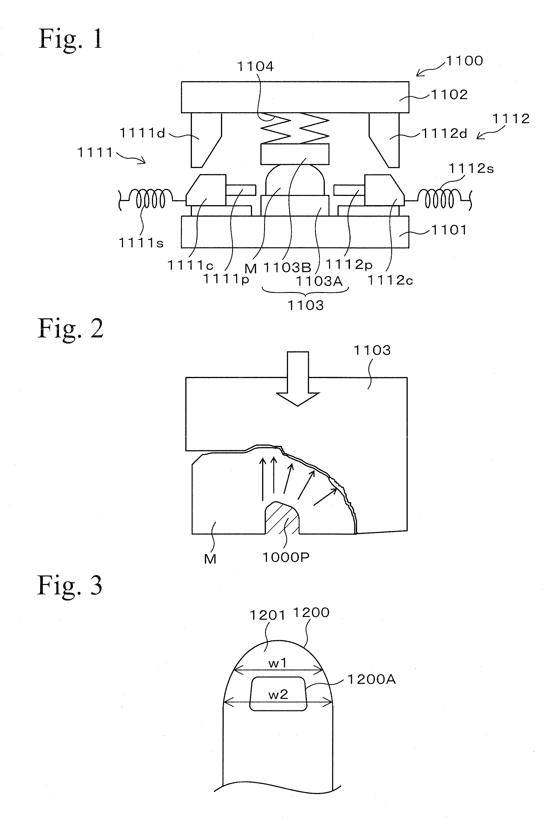
[0079]An embodiment of the first aspect of the invention is explained with reference to Figures hereinafter. FIG. 1 is a conceptual diagram for an explanation of movement of a forging apparatus 1100 used in a method for producing a crankshaft of the first embodiment. In FIG. 1, each portion of the forging apparatus 1100 (especially a die set 1103) is simply shown.

[0080]In the forging apparatus 1100, for example, a press bolster 1101 is provided thereto and a press ram 1102 is held above the press bolster 1101. A die set 1103 is disposed between the press bolster 1101 and the press ram 1102.

[0081]The die set 1103 is provided with a lower die 1103A, an upper die 1103B and side-forming punches 1111p and 1112p. The upper die 1103B is movably arranged with respect to the lower die 1103A. Reference numeral 1104 in FIG. 1 is a load-adjusting portion (an oil or an air pressure means) for adjusting the initial load with respect to the upper die 1103B. A material M is dispo...

second embodiment

2. Second Embodiment

2-1. Structure in Second Embodiment

[0093]An embodiment of the second aspect of the invention (the second embodiment) is explained referring to Figs. FIG. 7 and FIGS. 8A and 8B are views showing schematic structures of a crankshaft production apparatus 2100. FIG. 7 is a schematic top view showing the total structure of the crankshaft production apparatus 2100, FIG. 8A is a schematic cross-sectional side view showing a structure taken along a line 8A to 8A′ in FIG. 7, and FIG. 8B is a schematic cross-sectional side view showing a structure taken along a line 8B to 8B′ in FIG. 7. In FIG. 7 and FIGS. 8A and 8B, for convenience of showing views, omission and simplification in views of each portion are made. Specifically, a press ram 2104 and a load adjusting portion 2105 are omitted in FIG. 7, an upper die 2103A and a lower die 2103B of a die set 2103 and cam holders 2113h to 2116h are simply shown in FIGS. 8A and 8B. For the convenience of showing views, relative pos...

third embodiment

3. Third Embodiment

3-1. Structure of Third Embodiment

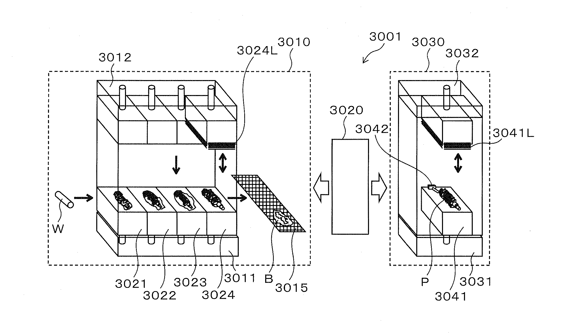
[0110]An embodiment of the third aspect of the invention (a third embodiment) is explained referring to the Figures hereinafter. FIG. 14 is a conceptual diagram showing a schematic structure of a crankshaft production apparatus 3100 in accordance with the third embodiment. FIG. 15 is a schematic top view showing a partial structure containing feed bars 3013 and 3014 of the crankshaft production apparatus 3100 shown in FIG. 14. In FIG. 14, the feed bars 3013 and 3014, clamp clicks 3013A to 3013D, 3113E, 3113F, 3014A to 3014D, 3114E, and 3114F shown in FIG. 15 are not shown in FIG. 14. A liner portion 3131 and a shim 3132 shown in FIGS. 16 and 17 are not shown in FIG. 14. For convenience, only one punch of a hollow forming mechanism 3142 shown in FIG. 15 is shown in FIG. 14. In the Figures for the third embodiment, the same reference symbols as those in FIGS. 20 to 23B indicate the same components as those in FIGS. 20 to 23B, and ex...


PUM

PropertyMeasurementUnit
temperatureaaaaaaaaaa
width w2aaaaaaaaaa
width w2aaaaaaaaaa

Abstract

A preformed product of a crankshaft is formed in a shape smaller than a shape of a cavity of a separatable die set 1103 composed of an upper die and a lower die and is disposed in the cavity of the die set 1103 as a material M. The cavity of the die set 1103 matches a required shape of the crankshaft. When the material M is disposed in the cavity of the die set 1103, a clearance is formed between the material M and the cavity, and when a side-forming punch 1000P is inserted into the material M, a hollow hole is formed in the material M and the cavity is filled with the material M. As a result, not only can weight saving be achieved by forming the hole in the crankpin of the crankshaft, but also degradation of dimensional accuracy by forming the hole can be avoided.

Description

BACKGROUND OF THE INVENTION[0001]1. Field of the Invention[0002]The present invention relates to a method for producing a crankshaft having a hollow hole, and relates to a production apparatus therefor.[0003]2. Related Art[0004]A crankshaft of an internal-combustion engine is provided with a journal shaft. A crankpin that is parallel to the journal shaft is connected thereto via an arm. A counterweight is formed in the arm, and the forming position of the counterweight with respect to the journal shaft is at the opposite side to the connecting position of the crankpin.[0005]In the crankshaft, from the viewpoint of improvement of fuel efficiency, weight saving by forming a hollow hole in the crankpin may be performed. When the hollow hole is formed in the crankpin, rigidity of the crankshaft is slightly affected by the forming of the hole, so that the hole is preferably formed in the crankpin. As a method for forming the hole, machining, and a method in which a crankpin is formed fro...

Claims


Application Information

Patent Timeline
Patent Type & Authority Applications(United States)
IPC IPC(8): B21K1/08B21J5/02
CPCB21J5/02B21J9/022Y10T29/49231B21J13/025B21K27/04Y10T29/17B21K1/08Y10T29/49286
Inventor OHNUMA, TAKAYUKIANDO, TSUTOMUITO, YASUHIRO
Owner HONDA MOTOR CO LTD
Why Eureka
Try Eureka