Phase shift mask blank, phase shift mask, and blank preparing method

a phase shift mask and mask technology, applied in the field of phase shift masks, can solve the problems of low dimensional accuracy and misalignment of pattern on the phase shift mask, and achieve the effects of reducing dimensional accuracy, improving quality and dimensional control, and minimizing pattern misalignmen

Active Publication Date: 2016-10-06
SHIN ETSU CHEM IND CO LTD
View PDF2 Cites 12 Cited by
  • Summary
  • Abstract
  • Description
  • Claims
  • Application Information

AI Technical Summary

Benefits of technology

[0039]The phase shift mask blank of the invention has a phase shift film which is thin enough to be advantageous for photomask pattern formation, improved in quality and dimensional control so as to minimize pattern misalignment and dimensional accuracy lowering during the step of patterning the phase shift film to manufacture a phase shift mask, and maintains a necessary phase shift for the phase shift function. Using the phase shift mask, lithography exposure complying with the requirements of pattern miniaturization and patterning accuracy becomes possible.

Problems solved by technology

When a phase shift mask is manufactured from this phase shift mask blank by patterning the phase shift film, a flatness change occurs before and after the pattern formation of the phase shift film, resulting in misalignment of the pattern on the phase shift mask, that is, a low dimensional accuracy.

Method used


Image

  • Phase shift mask blank, phase shift mask, and blank preparing method
  • Phase shift mask blank, phase shift mask, and blank preparing method

Examples


example 1

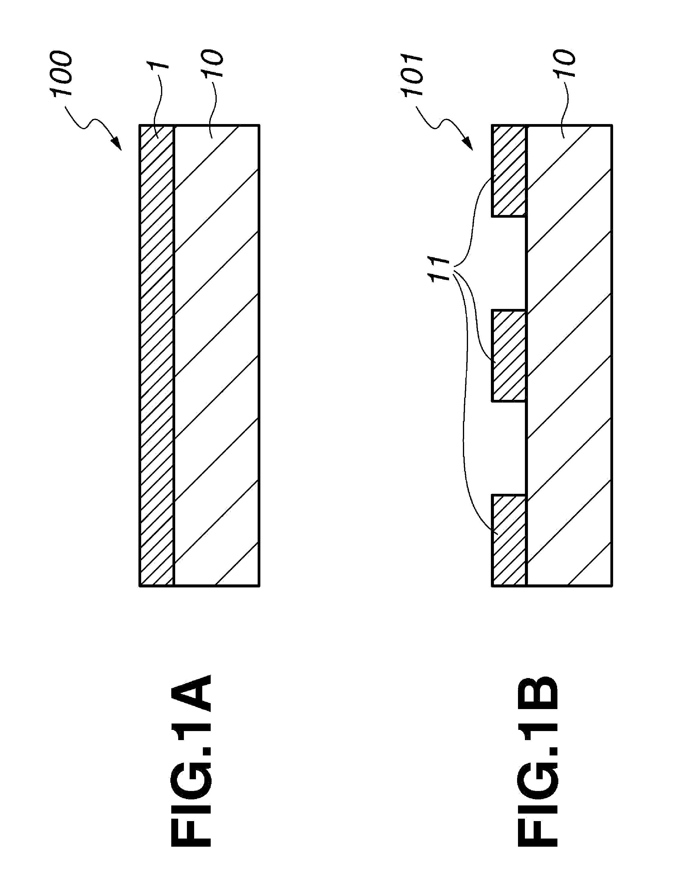
[0097]In a chamber of a sputtering system, a 6025 quartz substrate of 152 mm squares and 6.35 mm thick was set. A halftone phase shift film of SiN was deposited by using a silicon target as the sputtering target and argon and nitrogen gases as the sputtering gas, applying a power of 1,900 W across the target, and adjusting the flow rate of argon gas to 17 sccm and the flow rate of nitrogen gas to 40 sccm. Before and after deposition of the halftone phase shift film, a warpage change (ΔTIR) in a central region of 142 mm squares on the substrate surface was measured by a flatness tester Tropel® UltraFlat 200 Mask (Corning Inc.). The absolute value of ΔTIR was 0.22 μm. Thereafter, the substrate was transferred to a heat treating furnace where heat treatment was carried out at 500° C. for 6 hours in an atmosphere containing nitrogen and oxygen gases under substantially atmospheric partial pressures, completing a halftone phase shift mask blank. Before the deposition of the halftone phas...

example 2

[0100]In a chamber of a sputtering system, a 6025 quartz substrate of 152 mm squares and 6.35 mm thick was set. A halftone phase shift film of SiON was deposited by using a silicon target as the sputtering target and argon, nitrogen and oxygen gases as the sputtering gas, applying a power of 1,900 W across the target, and adjusting the flow rate of argon gas to 15 sccm, the flow rate of nitrogen gas to 40 sccm, and the flow rate of oxygen gas to 2 sccm. Thereafter, the substrate was transferred to a heat treating furnace where heat treatment was carried out at 500° C. for 6 hours in an atmosphere containing nitrogen and oxygen gases under substantially atmospheric partial pressures, completing a halftone phase shift mask blank. Before the deposition of the halftone phase shift film and after the heat treatment, the warpage change (ΔTIR) in a central region of 142 mm squares on the substrate surface had an absolute value of 0.15 μm. The halftone phase shift film after heat treatment ...

example 3

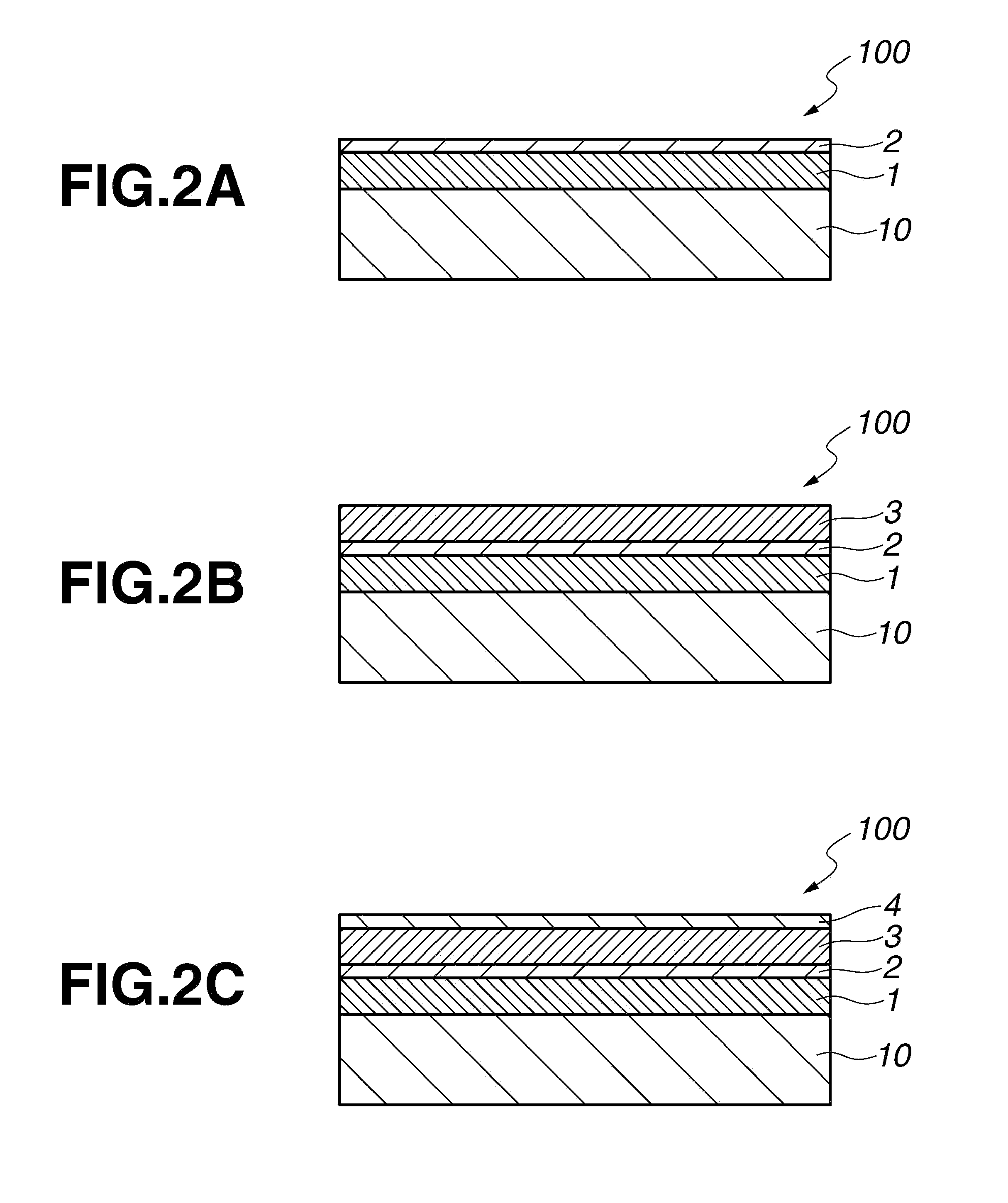
[0102]In a chamber of a sputtering system, a 6025 quartz substrate of 152 mm squares and 6.35 mm thick was set. Sputter deposition was carried out by using a silicon target as the sputtering target and argon, nitrogen and oxygen gases as the sputtering gas, and applying a power of 1,900 W across the target. A layer of SiN was deposited by adjusting the flow rate of argon gas to 15 sccm and the flow rate of nitrogen gas to 40 sccm, and a layer of SiON was then deposited by adjusting the flow rate of argon gas to 10 sccm, the flow rate of nitrogen gas to 40 sccm, and the flow rate of oxygen gas to 10 sccm. There was obtained a halftone phase shift film consisting of the SiN layer and SiON layer. Thereafter, the substrate was transferred to a heat treating furnace where heat treatment was carried out at 500° C. for 6 hours in an atmosphere containing nitrogen and oxygen gases under substantially atmospheric partial pressures, completing a halftone phase shift mask blank. Before the dep...


PUM

PropertyMeasurementUnit
thickaaaaaaaaaa
thickaaaaaaaaaa
thicknessaaaaaaaaaa

Abstract

In a phase shift mask blank comprising a transparent substrate and a phase shift film deposited thereon and having a phase shift of 150-200° with respect to sub-200 nm light, the phase shift film is composed of a silicon base material consisting of silicon, nitrogen and optionally oxygen, has a thickness of up to 70 nm, and provides a warpage change of up to 0.2 μm in a central region of a surface of the substrate before and after the deposition of the phase shift film on the substrate.

Description

CROSS-REFERENCE TO RELATED APPLICATION[0001]This non-provisional application claims priority under 35 U.S.C. §119(a) on Patent Application No. 2015-072766 filed in Japan on Mar. 31, 2015, the entire contents of which are hereby incorporated by reference.TECHNICAL FIELD[0002]This invention relates to a phase shift mask for use in the microfabrication of semiconductor integrated circuits or the like, a phase shift mask blank, and a method for preparing the mask blank.BACKGROUND ART[0003]In the field of semiconductor technology, research and development efforts are continued for further miniaturization of pattern features. Recently, as advances including miniaturization of circuit patterns, thinning of interconnect patterns and miniaturization of contact hole patterns for connection between cell-constituting layers are in progress to comply with higher integration density of LSIs, there is an increasing demand for the micropatterning technology. Accordingly, in conjunction with the tec...

Claims


Application Information

Patent Timeline
Patent Type & Authority Applications(United States)
IPC IPC(8): G03F1/32
CPCG03F1/32G03F1/26G03F1/82H01L21/02631H01L21/0337H01L2924/01007H01L2924/01008H01L2924/01014G03F1/20
Inventor INAZUKI, YUKIOKOSAKA, TAKURO
Owner SHIN ETSU CHEM IND CO LTD
Why Eureka
Try Eureka