Bending apparatus

a technology of bending apparatus and bending chamber, which is applied in the direction of shaping tools, forging/pressing/hammering apparatus, heating/cooling devices, etc., can solve the problems of increasing the cycle time and reducing the productivity of the bending apparatus b>0/b>, so as to prevent a reduction in the dimensional accuracy and increase the dimensional accuracy

Inactive Publication Date: 2013-08-20
NIPPON STEEL CORP +1
View PDF10 Cites 11 Cited by
  • Summary
  • Abstract
  • Description
  • Claims
  • Application Information

AI Technical Summary

Benefits of technology

[0018]As a result of diligent investigations for solving the above-described problems, the present inventors found that the above-described problems (a)-(f) can be solved by using an industrial robot of the vertically articulated type, for example, as at least a feed device and , if necessary, using an industrial robot of the vertically articulated type, for example, as a support device for a movable roller die or as a device for preventing a reduction in dimensional accuracy installed on the exit side of the movable roller die in order to increase dimensional accuracy. As a result of further investigations, they completed the present invention.
[0025]the deformation preventing mechanism being disposed at a fifth position which is located downstream of the fourth position in the direction for feeding the metal blank, and capable of preventing deformation of the fed metal blank.
[0026]According to the present invention, the above-described problems (a)-(f) of bending apparatus 0 can be solved. Thus, the present invention can provide a bending apparatus which has much higher productivity, occupies less space, and is easier to maintain than bending apparatus 0, and can manufacture long metal bent members having a closed cross section with high dimensional accuracy.

Problems solved by technology

(a) A feed device 3 using a ball screw or the like needs to be set up in accordance with the type of steel pipe 1. The set-up requires a considerable time. As a result, the cycle time of the bending apparatus 0 is increased and its productivity is degraded. In addition, when the path line of the steel pipe 1 is changed, it is necessary to adjust the installation position of the feed device 3 in accordance with the change in the path line, leading to a decrease in the productivity of the bending apparatus 0.
(b) A feed device 3 using a ball screw or the like feeds a steel pipe 1 by driving the ball screw after the steel pipe 1 has been set in the feed device. Therefore, it is difficult to shorten the production tact time.
(c) It is necessary to synchronize the operational timing of a feed device 3 using a ball screw or the like and a movable roller die 4. However, it is difficult to accurately synchronize them, and if they are not accurately synchronized, the dimensional accuracy of a bent member becomes worse.

Method used


Image

  • Bending apparatus
  • Bending apparatus
  • Bending apparatus

Examples


Embodiment Construction

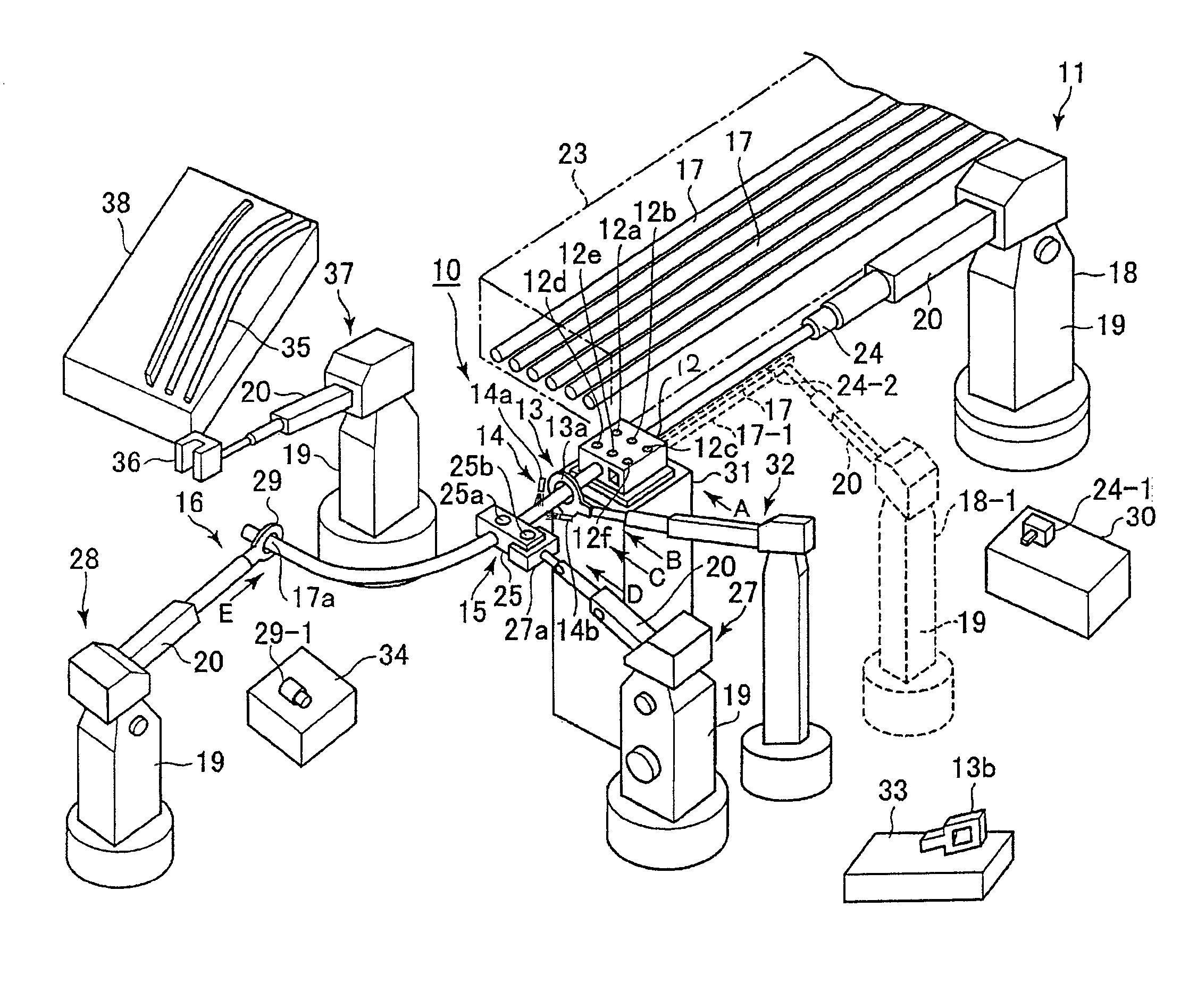
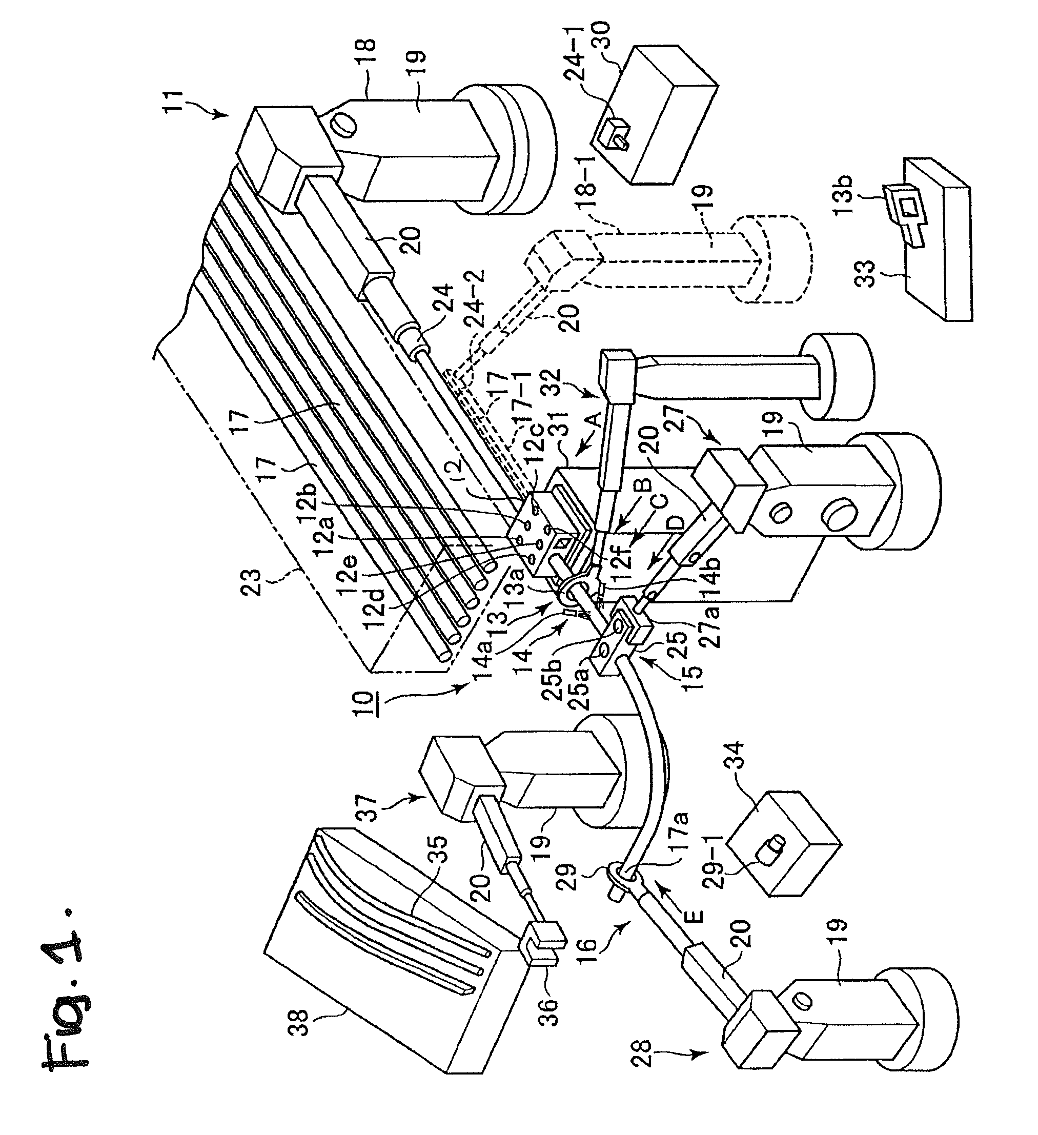
[0075]Below, an embodiment of a bending apparatus according to the present invention will be explained. In the following explanation, an example will be given of the case in which a “hollow metal blank having a closed cross section” in the present invention is a steel pipe 17. The present invention is not limited to bending of a steel pipe, and it can be applied in the same manner to any hollow metal blank having a closed cross section.

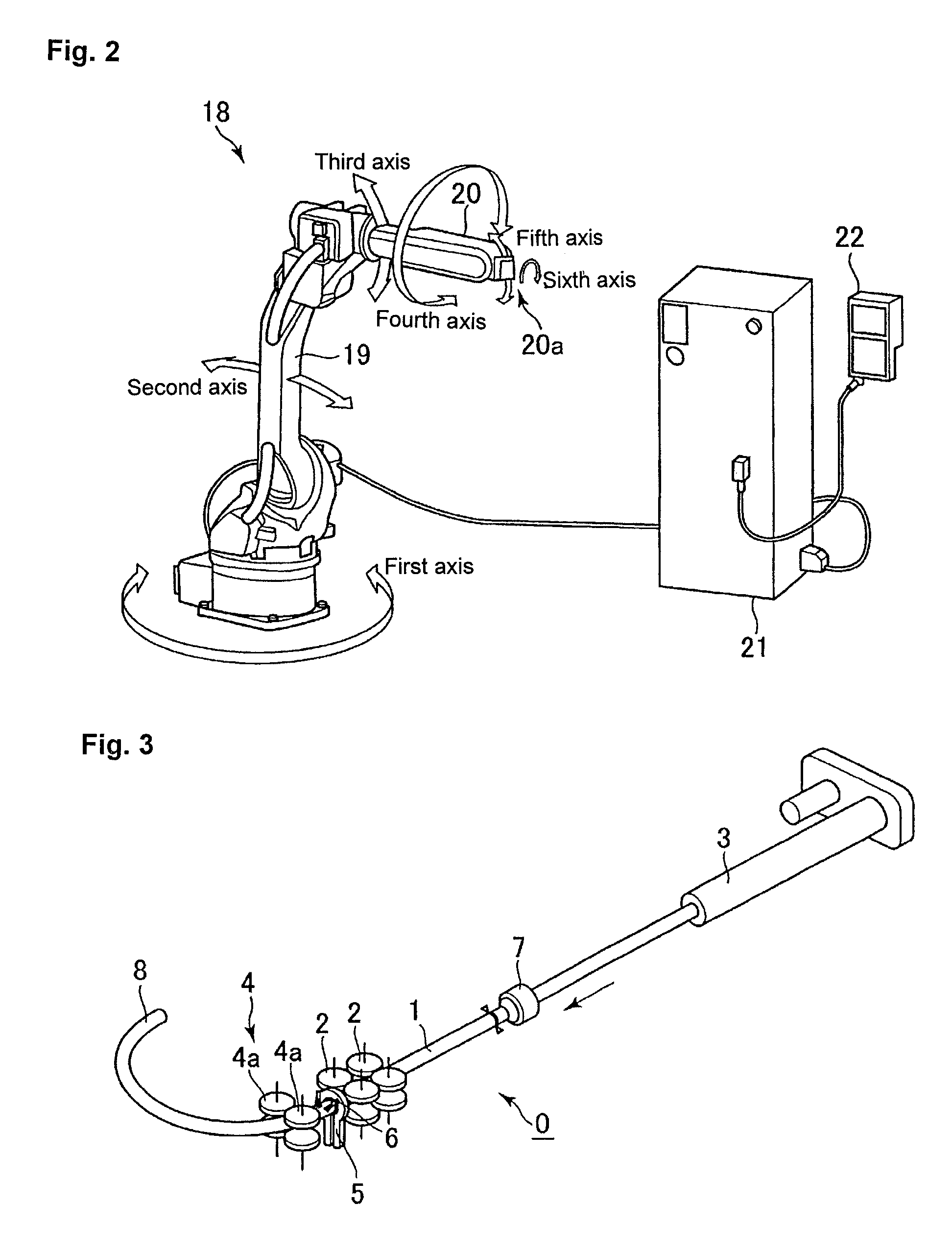
[0076]FIG. 1 is a perspective view schematically showing the structure of a bending apparatus 10 according to the present invention in partially simplified and abbreviated form. In FIG. 1, a total of 6 industrial robots including a first industrial robot 18 through a third industrial robot 28 are shown with their manipulators and the like illustrated in schematic and simplified form.

[0077]The bending apparatus 10 comprises a feed mechanism 11, a first support mechanism 12, a heating mechanism 13, a cooling mechanism 14, a second support mechanism 15, ...


PUM

PropertyMeasurementUnit
temperatureaaaaaaaaaa
bending momentaaaaaaaaaa

Abstract

A bending apparatus for manufacturing a bent member from a steel pipe with high dimensional accuracy and high productivity can be installed in a small space with good maintainability. The apparatus has a feed mechanism for feeding a steel pipe in its lengthwise direction, a first support mechanism for supporting the steel pipe while feeding it, a heating mechanism for heating a part or all of the steel pipe being fed, a cooling mechanism for cooling the portion of the heated steel pipe being fed, a second support mechanism for imparting a bending moment to the heated portion of the steel pipe to bend the steel pipe into a desired shape by moving two-dimensionally or three-dimensionally while supporting the fed steel pipe in at least one location, and a deformation preventing mechanism for preventing deformation of the steel pipe. The feed mechanism is a vertically articulated robot having seven axes.

Description

TECHNICAL FIELD[0001]This invention relates to a bending apparatus having an industrial robot as a component. Specifically, the present invention relates to a bending apparatus for manufacturing a bent member by applying two-dimensional or three-dimensional bending to a long metal blank having a closed cross section.BACKGROUND ART[0002]Strength members, reinforcing members, or structural members made of metal and having a bent shape are used in automobiles and various types of machines and the like. These bent members need to have a high strength, a light weight, and a small size. This type of bent member has been manufactured by welding of press formed members, punching of a plate, forging, and the like. However, it is difficult to further reduce the weight and size of bent members manufactured by these manufacturing methods.[0003]In recent years, the manufacture of this type of bent member by the so-called tube hydroforming technique has been actively studied (see Non-Patent Docum...

Claims


Application Information

Patent Timeline
Patent Type & Authority Patents(United States)
IPC IPC(8): B21D43/10
CPCB21D7/12B21D7/165B21D7/162B21D7/16
Inventor KUWAYAMA, SHINJIROTOMIZAWA, ATSUSHIINOUE, SABURO
Owner NIPPON STEEL CORP
Why Eureka
Try Eureka