

Traverse of light scribe disk drive
- Summary
- Abstract
- Description
- Claims
- Application Information
AI Technical Summary
Benefits of technology
Problems solved by technology
Method used
Image

Examples
Embodiment Construction
[0025]The technologies, methods and effects for achieving the above objects of the invention are disclosed in a number of preferred embodiments with accompanying drawing and disclosures.
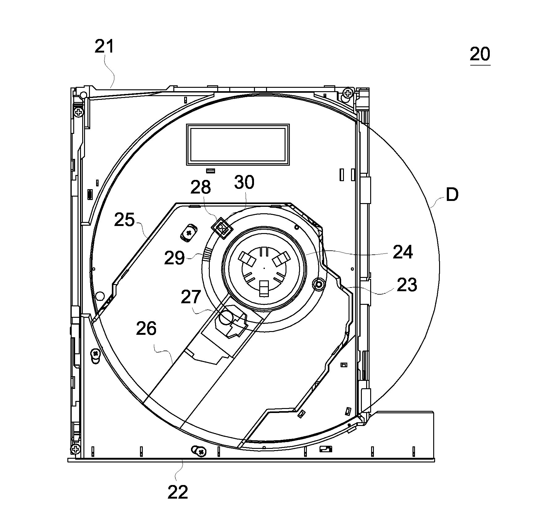
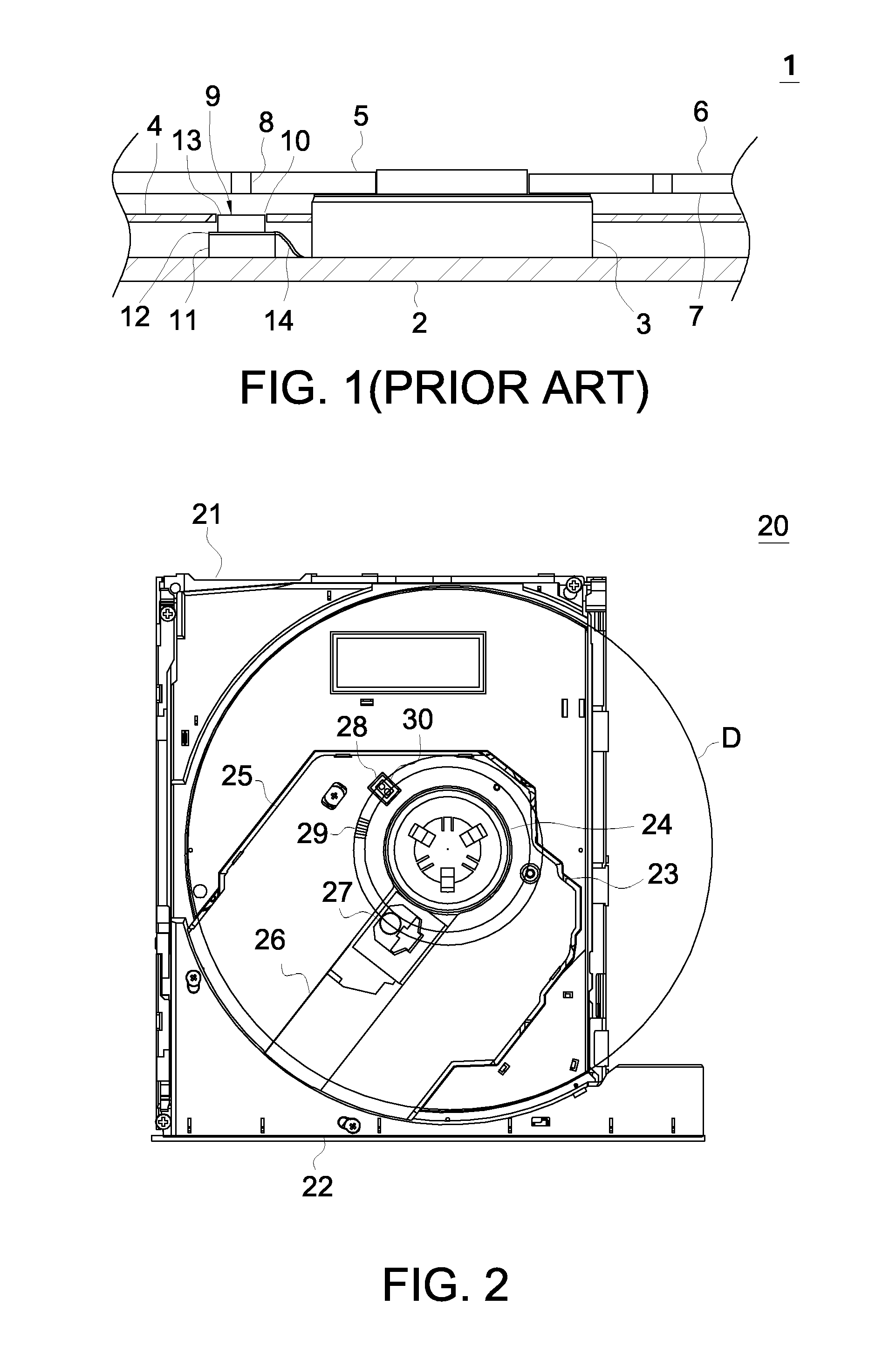
[0026]Referring to FIG. 2, a top view of a light scribe disk drive 20 of the invention is shown. On the part of the light scribe disk drive 20, a tray 22 can slide into or from the interior of a hollowed housing 21. A traverse 23 is disposed in the tray 22, and a spindle motor module 24 is disposed on one end of the traverse 23 and located at the center of the tray 22. A thin protection piece 25 is coated on the traverse 23 and around the spindle motor module 24. A long groove 26 is disposed along the radial direction of the spindle motor module 24 for the pick-up head 27 to slide back and forth. The protection piece 25 averts the long groove 26 of the pick-up head 27, and a squared hole 28 is disposed on the peripheral of the spindle motor module 24 and aligned with a bar code 29 of the optical disk...
PUM
 Abstract
Description
Claims
Application Information