
Distributed engine control systems and gas turbine engines

Inactive Publication Date: 2010-09-30
HONEYWELL INT INC
View PDF23 Cites 46 Cited by
  • Summary
  • Abstract
  • Description
  • Claims
  • Application Information

AI Technical Summary

Benefits of technology

[0005]Distributed engine control systems and gas turbine engines are provided.
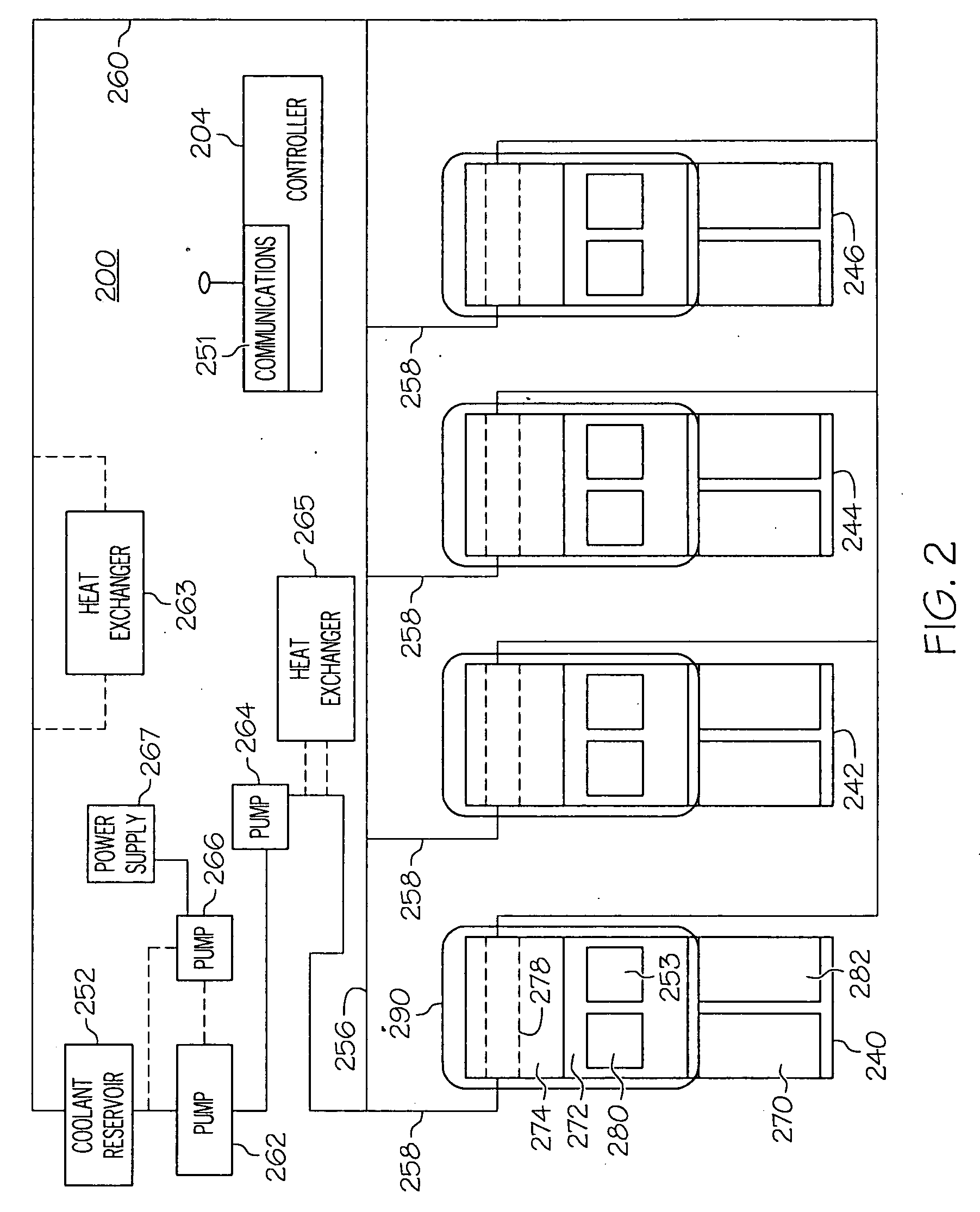
[0006]In an embodiment, by way of example only, a distributed engine control system includes a central controller, a plurality of nodes in operable communication with the central controller, each node including an electronic circuit and a heat transfer element adapted to absorb heat from the electronic circuit, each node in operable communication with the central controller, and a coolant distribution system including a plurality of coolant interfaces, a coolant line, and a coolant source, each coolant interface of the plurality of coolant interfaces adapted to contain a coolant that is adapted to absorb heat from the heat transfer element of a node of the plurality of nodes, and the coolant line adapted to provide fluid communication between the nodes of the plurality of nodes and the coolant source.
[0007]In another embodiment, by way of example only, a gas turbine engine includes an intake section, a compressor section in flow communication with the intake section, a combustion section in flow communication with the compressor section, a turbine section in flow communication with the combustion secti

Problems solved by technology

For example, because the FADEC typically communicates with each sensor and actuator using wiring and multiple wiring harnesses, the overall weight and cost of the system may be undesirably high.
Additionally, identifying a specific part of the FADEC that may need repair or replacement may take more time than desired.

Method used


Image

  • Distributed engine control systems and gas turbine engines
  • Distributed engine control systems and gas turbine engines
  • Distributed engine control systems and gas turbine engines

Examples


Embodiment Construction

[0012]The following detailed description is merely exemplary in nature and is not intended to limit the inventive subject matter or the application and uses of the inventive subject matter. Furthermore, there is no intention to be bound by any theory presented in the preceding background or the following detailed description.

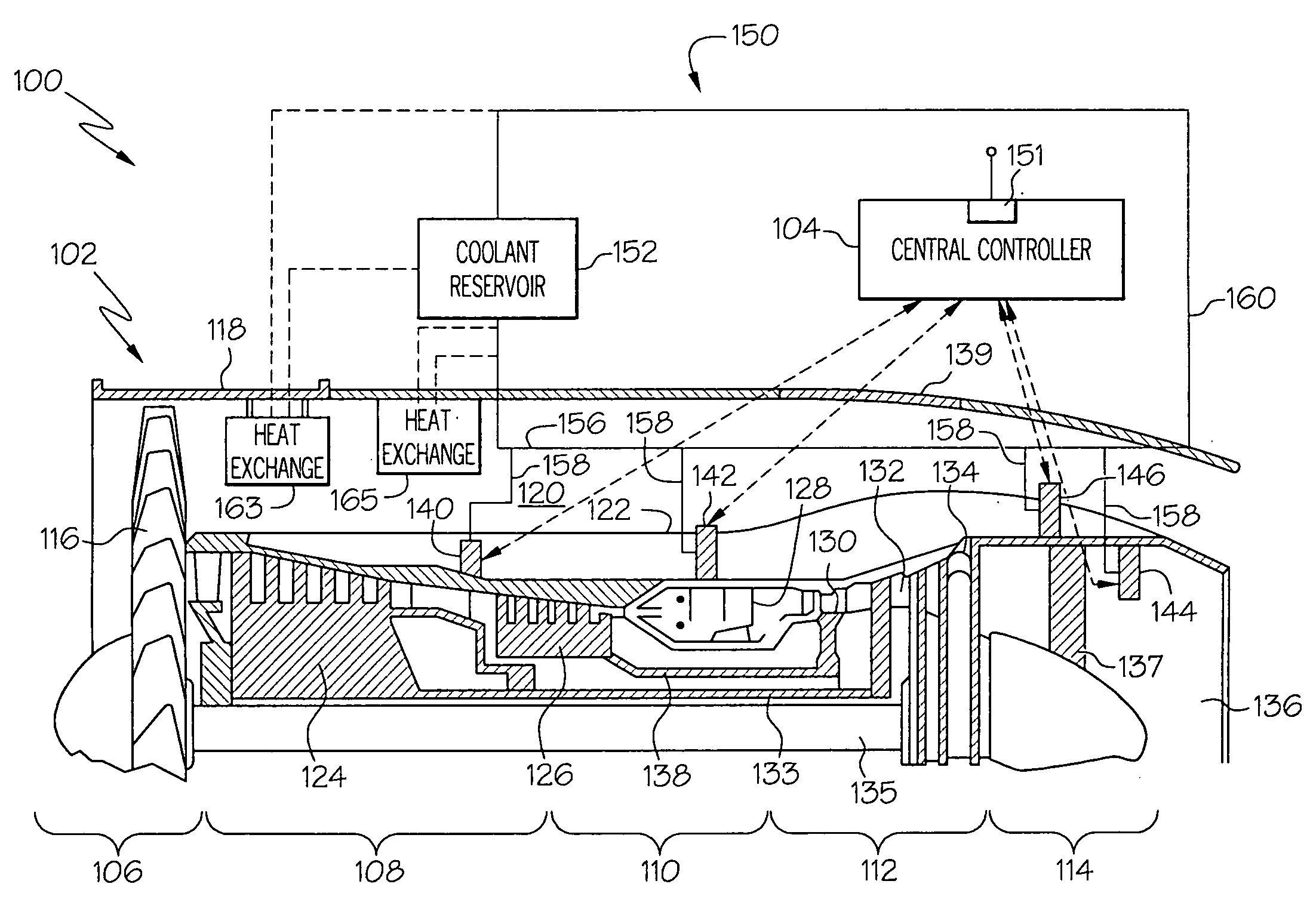
[0013]FIG. 1 is a simplified cross section view of a portion of an aircraft 100, according to an embodiment. The aircraft 100 is configured to include a distributed engine control system including various components that are located on or within an engine 102, in an embodiment. In another embodiment, the distributed engine control system may include one or more components that may be disposed at other locations throughout the aircraft 100, such as on an aircraft wing, on or around an inlet door or another section of the aircraft 100. In any case, one or more of the components of the distributed engine control system are thermally coupled to a coolant distributio...


PUM


Abstract

Distributed engine control systems and gas turbine engines are provided. In an embodiment, a distributed engine control system includes a central controller, a plurality of nodes in operable communication with the central controller, each node including an electronic circuit and a heat transfer element adapted to absorb heat from the electronic circuit, each node in communication with the central controller, and a coolant distribution system including a plurality of coolant interfaces, a coolant line, and a coolant source, each coolant interface of the plurality of coolant interfaces adapted to contain a coolant that is adapted to absorb heat from the heat transfer element of a node of the plurality of nodes, and the coolant line adapted to provide fluid communication between the nodes of the plurality of nodes and the coolant source

Description

TECHNICAL FIELD[0001]The inventive subject matter generally relates to gas turbine engines, and more particularly relates to distributed control systems for gas turbine engines.BACKGROUND[0002]A gas turbine engine control system typically includes a plurality of sensors and a plurality of actuators. In most cases, sensors may be implemented at various locations in an engine and may be employed to detect engine performance parameters, such as turbine rotational velocities, engine pressures, engine temperatures, and / or other controlled parameters, such as fuel flow and inlet guide vane positions. The sensors supply feedback signals representative of the detected data to a central processing unit such as, for example, a Full Authority Digital Engine Controller (FADEC). In response to the feedback signals, the FADEC generates and supplies appropriate actuator commands to one or more of the actuators to thereby control engine operation. For example, the actuators may be used to control t...

Claims


Application Information

Patent Timeline
IPC IPC(8): F02C9/00F02C7/12H05K7/20
CPCF02C7/12F02C7/224F02C9/16Y02T50/675F02K3/105H05K7/20218Y02T50/671F02C9/30Y02T50/60
Inventor SLOAT, JEFBENSON, DWAYNE MICHAELSTANGE, KENT
Owner HONEYWELL INT INC
Learn More