Vehicle body structure

a technology for vehicles and body parts, applied in the direction of roofs, movable seats, transportation and packaging, etc., can solve the problems of floor tunnel distortion and deformation, prevent distortion or deformation, reduce the amount of load, and reduce the protruding length of the left side rim part and the right side rim part of the load receiving member

Inactive Publication Date: 2010-09-30
HONDA MOTOR CO LTD
View PDF9 Cites 8 Cited by
  • Summary
  • Abstract
  • Description
  • Claims
  • Application Information

AI Technical Summary

Benefits of technology

[0008]According to the vehicle body structure described in (1) above, the left floor cross member and the right floor cross member support the load entered from the seat to the load receiving member when a lateral collision occurs. Thus, it is possible to reduce the amount of load which is entered directly to the floor tunnel from the load receiving member. Therefore, the floor tunnel is prevented from distorting or deforming. In addition, the load entered to the seat can be quickly transmitted to the floor of the vehicle body.
[0009]According to the vehicle body structure described in (2) above, the left side rim part and the right side rim part of the load receiving member are linked to the left floor cross member and the right floor cross member via the upper cross member. Thus, the length of protrusion of the left side rim part and the right side rim part of the load receiving member can be shortened. At the same time, the upper cross member can further enhance the rigidity of the connecting portion between the left floor cross member and the right floor cross member.
[0010]According to the vehicle body structure described in (3) above, the left side rim part and the right side rim part of the load receiving member are fastened to the upper surface of the upper cross member. As a result, the fastening operation can be conducted easily from the upper and lower directions. In this way, the operability of assembling the vehicle body structure can be improved.

Problems solved by technology

Therefore, there is a concern in that the floor tunnel might be distorted and deformed.

Method used


Image

  • Vehicle body structure
  • Vehicle body structure
  • Vehicle body structure

Examples


first embodiment

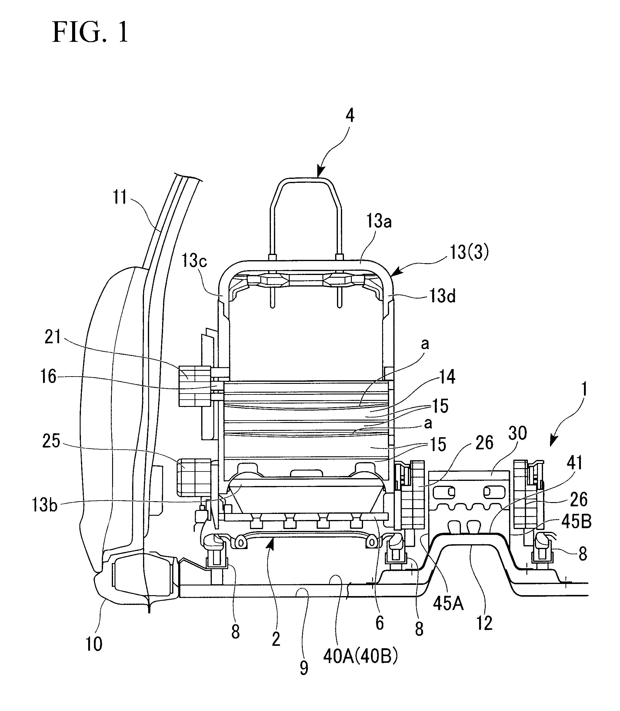
[0014]Hereunder, the present invention is described with reference to FIGS. 1-3.

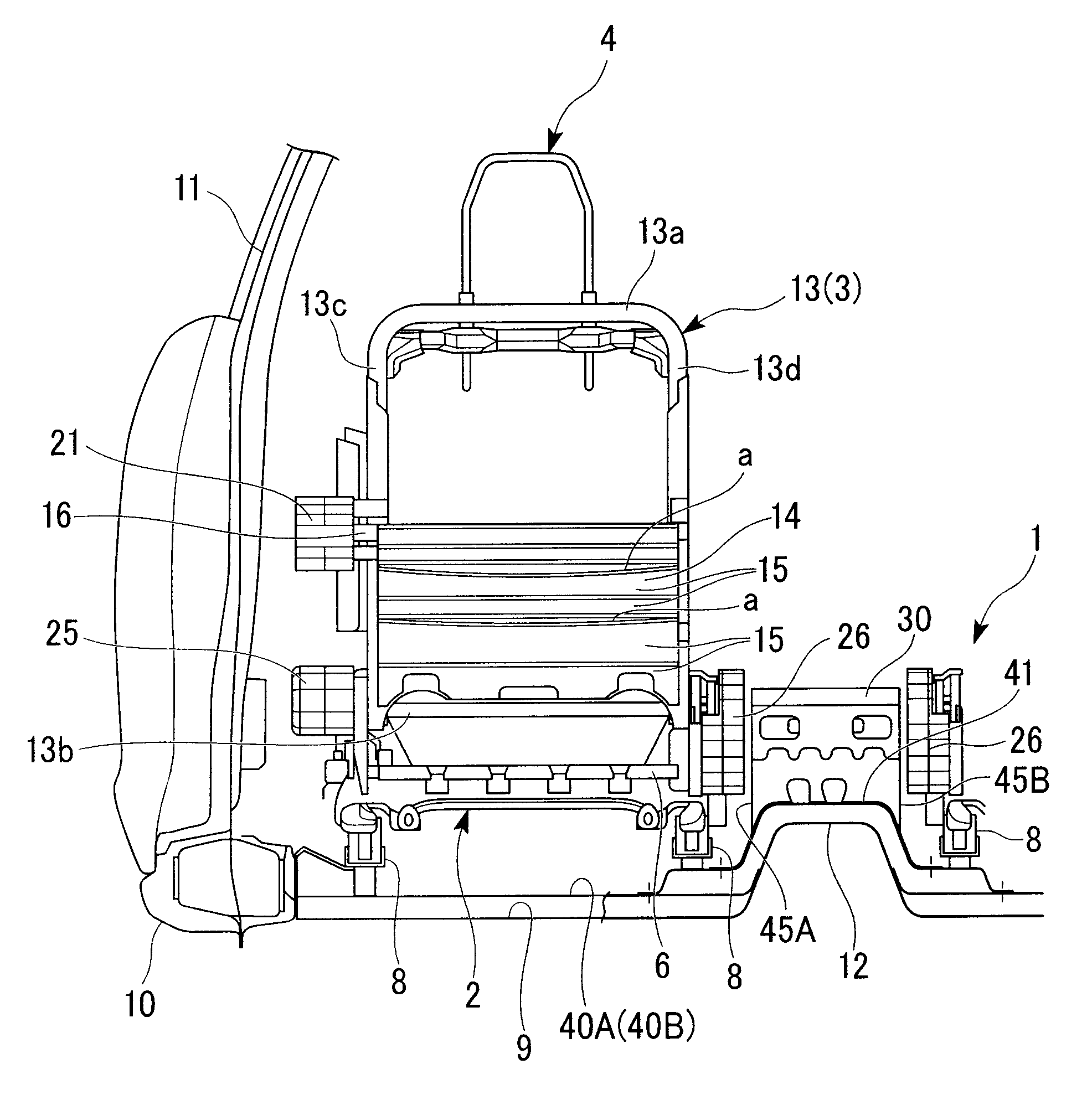
[0015]FIG. 1 is a diagram of a left seat 1 and a right seat 1 at a front row of a vehicle seen from a back side. FIG. 1 is drawn so as to show only a skeletal member of seat 1. In addition, only a portion of the right seat 1 is shown.

[0016]The seat 1 includes a seat cushion 2 which supports a bottom of a passenger, a seat back 3 which is linked to a rear end part of the seat cushion 2 and supports a hip and a chest (a back) of the passenger, and a head rest 4 which is supported by an upper part of the seat back 3 and supports a head and a neck of the passenger.

[0017]The seat cushion 2 includes a cushion frame at a rear end part of the seat cushion 2. A rear part cross member 6 is fastened to the cushion frame. The rear part cross member 6 extends along the vehicle width direction. This cushion frame is provided on a vehicle body floor 9 via a seat rail 8, 8 so that the cushion frame can slide in the fron...


PUM


Abstract

A vehicle body structure includes: a floor tunnel bulging from a center of a floor of a vehicle chamber; a pair of seats flanking the floor tunnel from left and right sides of the floor tunnel; a load receiving member placed on an upper part of the floor tunnel; a left floor cross member extending from a left side of the floor tunnel in the vehicle width direction; and a right floor cross member extending from a right side of the floor tunnel in the vehicle width direction. The load receiving member contacts the seat when the seat receives an impact load from a side of the vehicle body. In addition, the load receiving member transmits the impact load to the floor of the vehicle body. Left and right side rim parts of the load receiving member are connected respectively to the left and right floor cross members.

Description

BACKGROUND OF THE INVENTION[0001]The present application claims priority on Japanese Patent Application No. 2009-074138, filed Mar. 25, 2009, the content of which is incorporated herein by reference.FIELD OF THE INVENTION[0002]The present invention relates to a vehicle body structure which transmits an impact load, entered from a side direction of the vehicle body, to a floor via a seat on which a passenger is seated.DESCRIPTION OF THE RELATED ART[0003]According to a known vehicle body structure, an impact load, entered to a seat from a side direction of the vehicle body when the vehicle collides laterally, is quickly transmitted to a floor of the vehicle body. This known vehicle body structure is configured so that an impact receiving member is placed on an upper part of a floor tunnel placed between a left seat and a right seat. The impact receiving member comes in contact with a side part of the seat when the vehicle collides laterally. In this way, the impact receiving member tr...

Claims


Application Information

Patent Timeline
Patent Type & Authority Applications(United States)
IPC IPC(8): B62D21/15B62D25/20
CPCB60N2/4235B62D25/20B60N2/42736
Inventor YAMAKI, JOGEN
Owner HONDA MOTOR CO LTD
Why Eureka
Try Eureka