
Extraction of depositional systems

a depositional system and seismic interpretation technology, applied in the field of 3d seismic interpretation, can solve the problems of increasing the volume of data to be interpreted for each project, increasing the difficulty of finding and developing energy resources, and increasing the difficulty of exploration and efficient development of hydrocarbon reserves, so as to improve both the structural interpretation and the results.

Inactive Publication Date: 2010-09-30
CGG JASON (NETHERLANDS) BV
View PDF57 Cites 47 Cited by
  • Summary
  • Abstract
  • Description
  • Claims
  • Application Information

AI Technical Summary

Benefits of technology

[0028]It is a further aspect of this invention to provide such a method and system in which noise in the seismic volume after acquisition and seismic processing is removed or minimized at each step in the workflow.
[0061]Since stratigraphic features are better imaged, more complete and more easily interpreted in the transformed domain, the workflow improves the efficiency, accuracy, and completeness of the interpretation of depositional systems when compared to other approaches.

Problems solved by technology

Energy resources are becoming steadily more difficult to find and develop.
While the problems of exploration and the efficient development of hydrocarbon reserves have become more difficult, the volume of data to be interpreted for each project has become orders of magnitude greater over the past 20 years.
However, in volumes with structural deformation, horizontal slices do not represent depositional surfaces for more than a small portion of the total volume.
Stark's approach assumes that unwrapped phase closely approximates geologic age, but this is an assumption that is often in error.
Both horizon slicing and proportional slicing generally suffer from substantial limitations in that they do not accommodate and compensate for generalized 3-D structural deformation subsequent to deposition, nor do they properly account for the wide variety of depositional environments.
Horizon and proportional slicing do not properly reconstruct paleo-depositional surfaces in other depositional environments, nor do they account for post-depositional structural changes (particularly faulting) or post-depositional erosion.
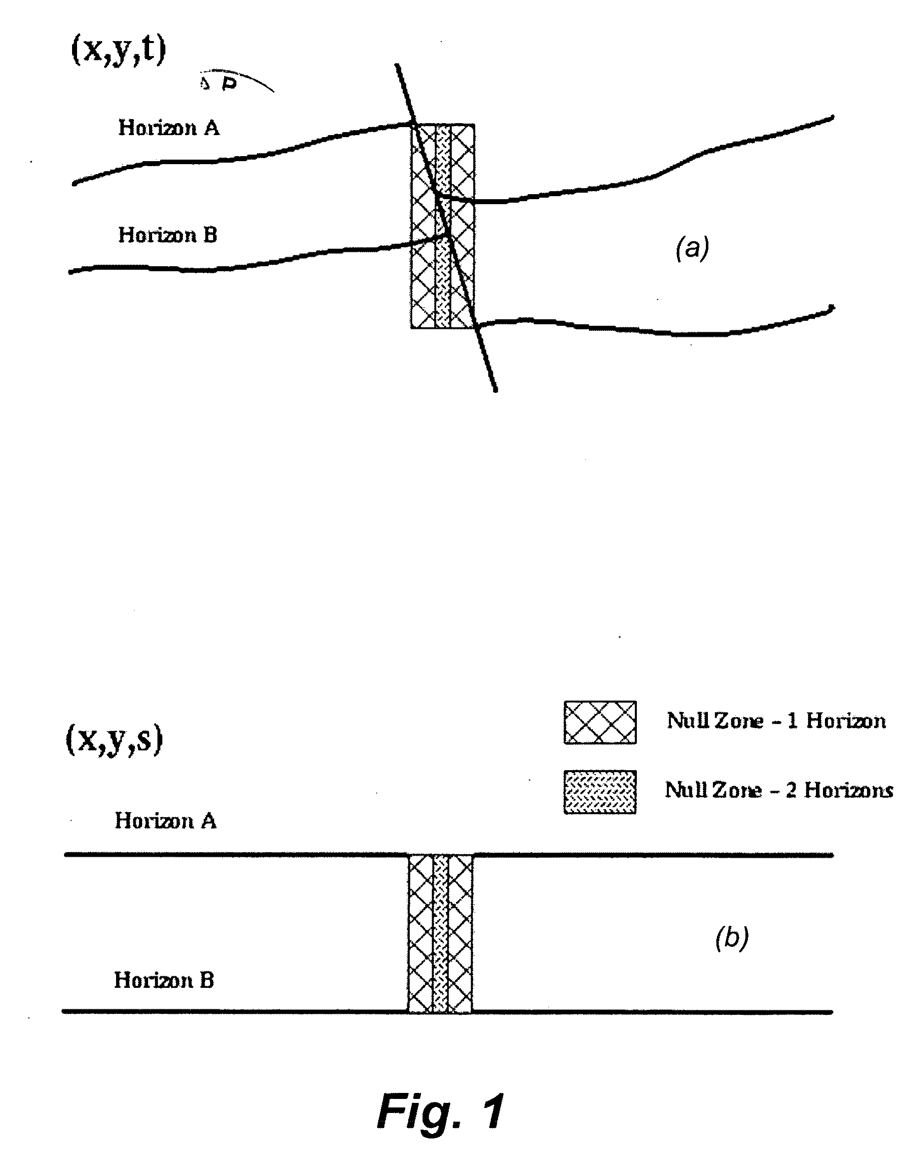
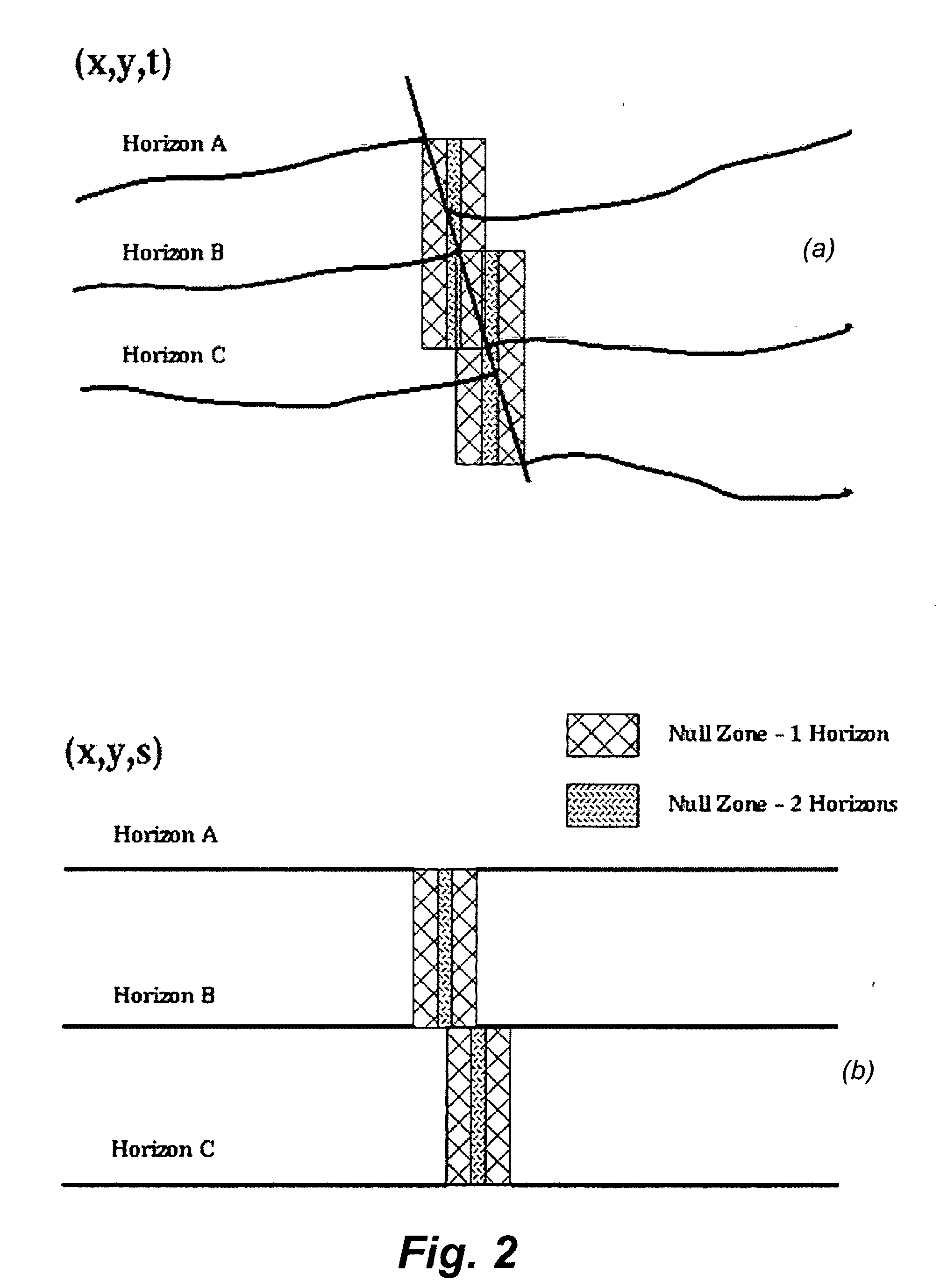
In most previous attempts to solve this problem, where this simple form of proportional slicing is implemented, the indeterminate zones are filled with input seismic data rather than nulls, which can be quite misleading.
The lack of interpreted structural control in their approach produces poor results for seismic volumes that contain any significant structural deformation.

Method used


Image

  • Extraction of depositional systems
  • Extraction of depositional systems
  • Extraction of depositional systems

Examples


example intervals

and Geometric Rules

[0140]The set of intervals included below is intended as a set of examples and is not inclusive of all the possible intervals that can be handled using the Domain Transformation approach. This subset is chosen for illustrative purposes. All types of geologic intervals can be handled using the approach presented for Domain Transformation.

[0141]Proportional Intervals:

[0142]Proportional intervals include conformable intervals and growth intervals, with or without post-depositional folding and differential compaction. For continuous unfaulted proportional intervals, such as in FIG. 8, three steps are performed. First, a global search is performed for all trace segments contained between the two bounding horizons. This search is meant to locate the thickest portion of the interval (ZM). The number of samples in this interval (N) at its maximum thickness is calculated by dividing this maximum time thickness by the sample rate (S) of the input data volume.

N=ZM / S

[0143]In...


PUM


Abstract

A process that assists with the identification of potential hydrocarbon deposits that includes performing a structural interpretation of a three-dimensional seismic volume, transforming the three-dimensional seismic volume into a stratal-slice volume, performing a stratigraphic interpretation of the stratal-slice volume which includes the extracting of bounding surfaces and faults and transforming the stratal-slice volume into the spatial domain. As illustrated in FIGS. 24a, b and c, an exemplary seismic volume before Domain Transformation is presented in FIG. 24a, interpreted horizons and faults used in the transformation are presented in FIG. 24b, and the Domain Transformed stratal-slice volume is presented in FIG. 24c. The input seismic volume in FIG. 24a has deformations associated with syn- and post-depositional faulting. The output Domain Transformed volume (FIG. 24c) is substantially free of deformations.

Description

RELATED APPLICATION DATA[0001]This application claims the benefit of and priority under 35 U.S.C. §119(e) to U.S. Patent Application Nos. 60 / 815,630, filed 21 Jun. 2006, entitled “Algorithm and Process to Create Geobody Bounding Surfaces,” 60 / 815,625, filed 21 Jun. 2006, entitled “Computed Aided and Automatic Extraction of Depositional Systems,” and 60 / 815,961, filed 21 Jun. 2006, entitled “Stratal-Slice Domain Transformation of a Seismic Volume,” all of which are incorporated herein by reference in their entirety.BACKGROUND[0002]An exemplary embodiment of this invention is in the field of 3-D interpretation, and more particularly to 3-D seismic interpretation. More specifically, an exemplary embodiment includes a workflow, including two new processes, implemented as software that is designed to enable automatic or semi-automatic interpretation of paleo-depositional features in three-dimensional seismic data for exploration, development and, for example, production of hydrocarbons.[...

Claims


Application Information

Patent Timeline
Patent Type & Authority Applications(United States)
IPC IPC(8): G06T15/00G06T11/20
CPCG01V1/30G01V2210/48G01V1/32
Inventor DORN, GEOFFREY A.HAMMON, III, WILLIAM S.CARLSON, JAMES A.
Owner CGG JASON (NETHERLANDS) BV
Learn More