
Mirror with monitor for vehicle

a technology for mirrors and vehicles, applied in vehicle components, instruments, polarising elements, etc., can solve the problems of difficult to view the image from the driver's seat, display devices capable of achieving higher luminance, tend to be bigger and heavier, and generate more heat. , to achieve the effect of suppressing the cost increase, increasing the amount of display light, and increasing the viewability of the display

Inactive Publication Date: 2010-09-30
MURAKAMI CORP
View PDF8 Cites 124 Cited by
  • Summary
  • Abstract
  • Description
  • Claims
  • Application Information

AI Technical Summary

Benefits of technology

[0007]The present invention has been made in view of the circumstances described above, and an object of the present invention is to provide a mirror with a monitor for a vehicle that has a region that transmits display light, in which the region is improved to have an adequate reflectance when the monitor provides no display and to transmit an increased amount of display light compared with conventional to increase the viewability of the display when the monitor provides display, while suppressing the cost increase involved with the improvement.
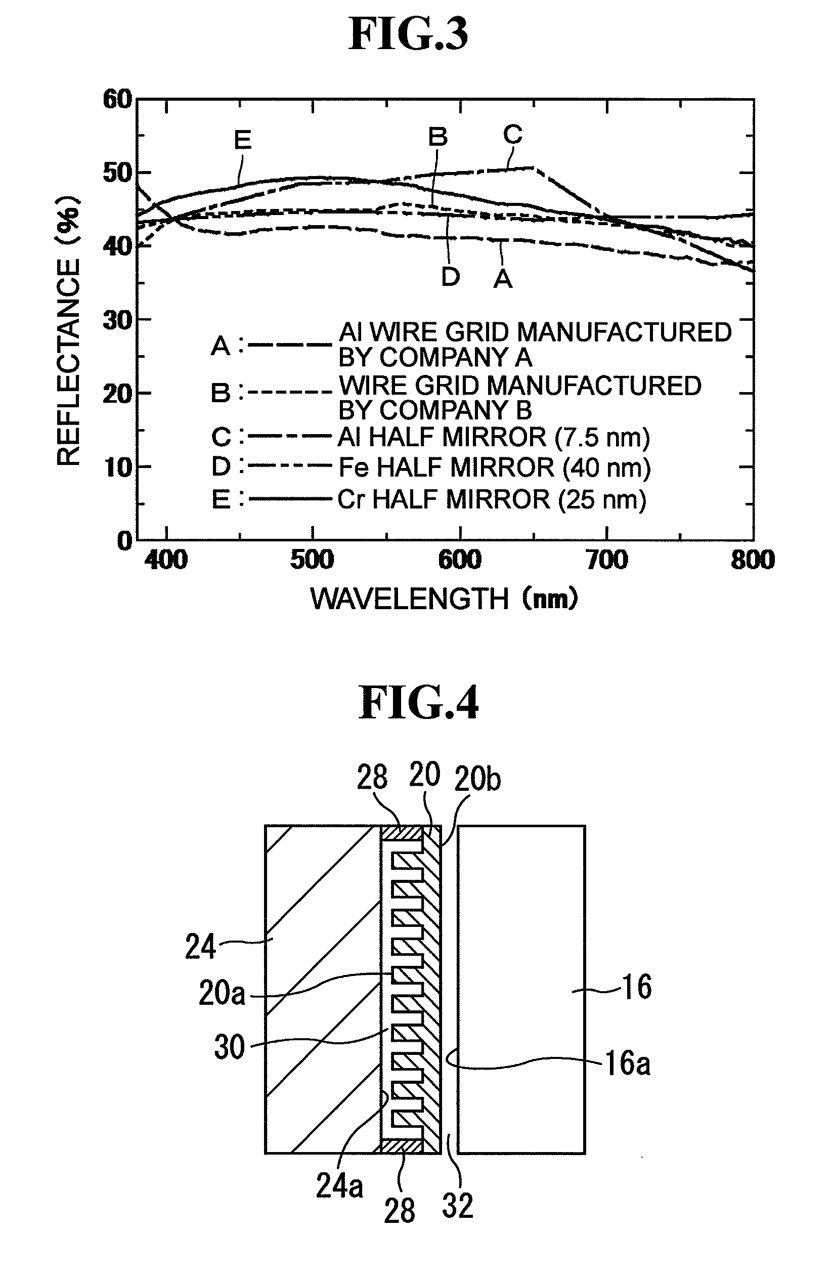
[0008]The present invention provides a mirror with a monitor for a vehicle that allows linearly polarized display light emitted from a light emitting display device to pass through a region of the mirror surface from a back side of the mirror surface thereof to be visually recognized by a viewer, wherein the region of the mirror surface through which the display light passes is formed of a reflective polarizing film having a polarization direction that agrees with the polarization direction of the display light, and a region of the mirror surface adjacent to the reflective polarizing film is formed of a reflective film formed of a reflective metal film or a dielectric multilayer film. According to the present invention, since the region of the mirror surface that transmits the display light is formed of a reflective polarizing film having a polarization direction that agrees with the polarization direction of the display light, the amount of display light transmitted increases and the viewability of the display is improved compared with the case where the region of the mirror surface that transmits the display light is formed of a half mirror. In addition, since the region adjacent to the reflective polarizing film is formed of a reflective metal film or a dielectric multilayer film, the mirror can be manufactured at lower cost than the mirror having the entire mirror surface formed of the expensive reflective polarizing film. The reflective metal film can be a Cr, Ni, Al, Fe, Ag or Pd film, for example.
[0009]According to the present invention, the region of the mirror surface adjacent to the reflective polarizing film can be forme

Problems solved by technology

That is, when the rear window is bright, such as in the daytime, the image displayed on the monitor is obscured by the bright rear window which is reflected on the mirror, and thereby, it is difficult to view the image from the driver's seat.
However, display devices capable of achieving higher luminance have problems that

Method used


Image

  • Mirror with monitor for vehicle
  • Mirror with monitor for vehicle
  • Mirror with monitor for vehicle

Examples


Embodiment Construction

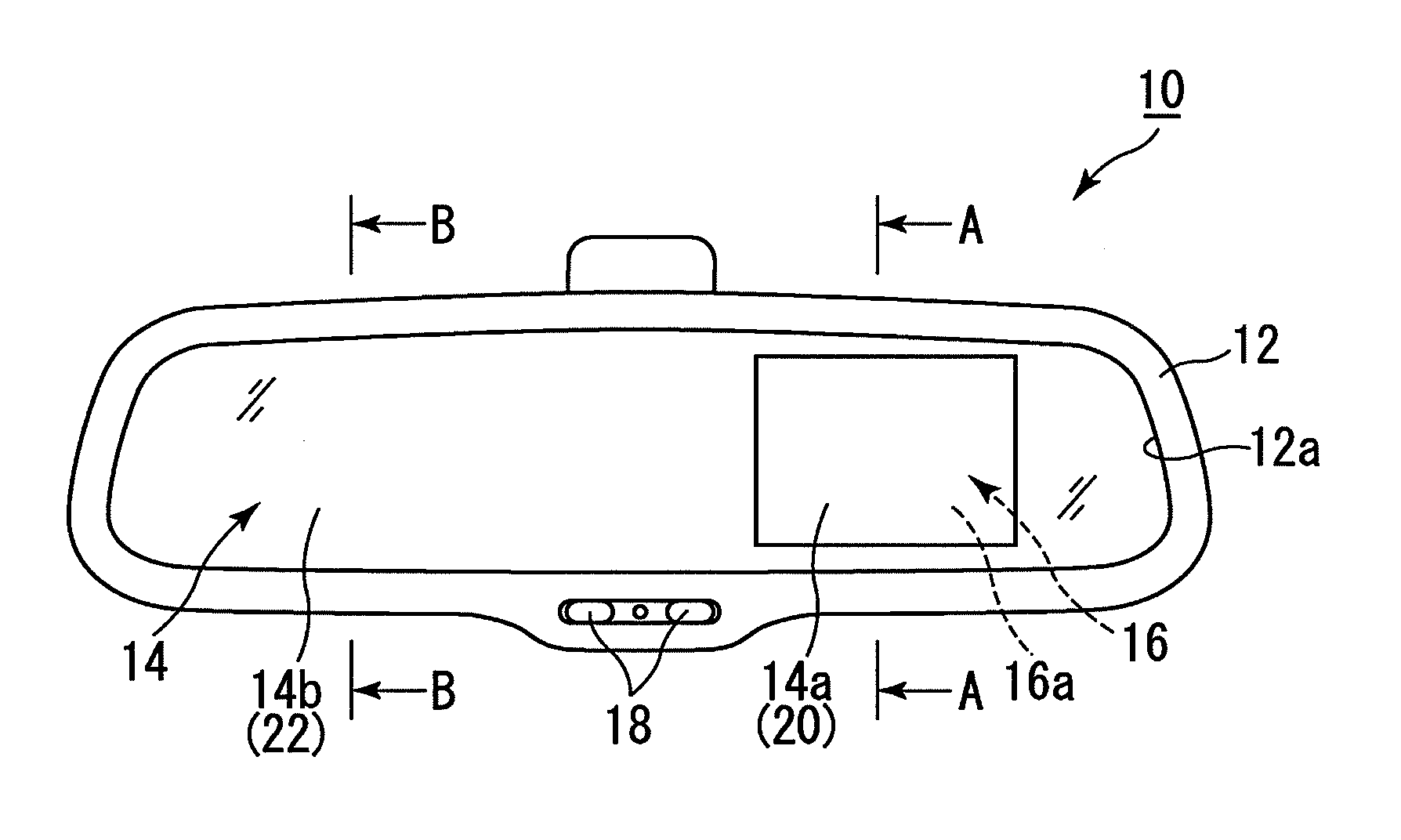
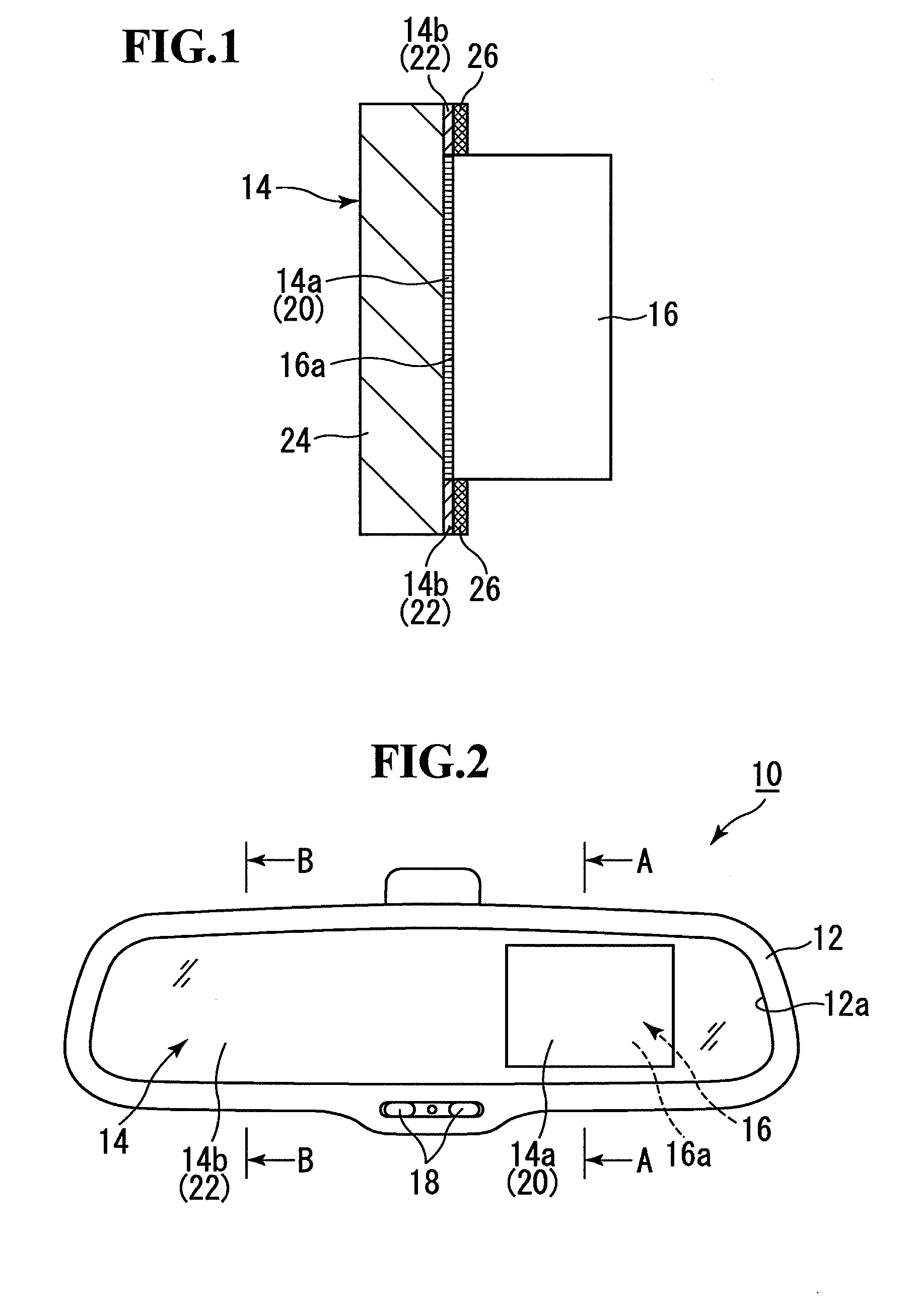
[0018]FIG. 2 is a diagram showing an inner mirror for a vehicle according to an embodiment of the present invention. In this embodiment described below, a reflective polarizing film is formed of a wire grid. An inner mirror 10 has a housing 12 and a mirror element 14 disposed in a front opening 12a of the housing 12. In a space in the housing 12 behind the mirror element 14, a liquid crystal monitor 16 is housed with a display surface 16a thereof facing the mirror element 14. A mirror surface of the mirror element 14 has a region 14a that faces the display surface 16a of the liquid crystal monitor 16 and a region 14b that surrounds the periphery of the region 14a. An operating element 18, such as an ON / OFF switch for the liquid crystal monitor 16, is disposed at a lower part of the front periphery of the housing 12. When the liquid crystal monitor 16 is turned on by manipulating the operating element 18, a backlight of the liquid crystal monitor 16 emits light to display information...


PUM


Abstract

To provide a mirror with a monitor for a vehicle that allows display light to pass through a region of a mirror surface thereof to be visually recognized by a viewer, in which the viewability of the display is improved while suppressing the cost increase. A region of a mirror element that transmits display light is formed of a wire grid having a polarization direction that agrees with the polarization direction of the display light. A region of the mirror element adjacent to the wire grid is formed of a reflective film formed of a reflective metal film or a dielectric multilayer film. The grid of the wire grid is formed of Al thin lines, for example. The reflective film is formed of a Cr half mirror, for example. A dark color mask is disposed on the back surface of the Cr half mirror.

Description

[0001]The disclosure of Japanese Patent Application No. JP2009-72371 filed on Mar. 24, 2009 including the specification, drawings, claims and abstract is incorporated herein by reference in its entirety.BACKGROUND OF THE INVENTION[0002]1. Field of the Invention[0003]The present invention relates to a mirror with a monitor for a vehicle that allows display light to pass through a region of a mirror surface thereof from a back side of the mirror surface to be visually recognized by a driver or the like, in which the region that transmits the display light is improved to have an adequate reflectance when the monitor provides no display and to transmit an increased amount of display light compared with conventional to increase the viewability of the display when the monitor provides display, while suppressing the cost increase involved with the improvement.[0004]2. Description of the Related Art[0005]In Japanese Patent Laid-Open Nos. 3-28947U, 9-220976, and 2002-120649, there are descri...

Claims


Application Information

Patent Timeline
IPC IPC(8): G02F1/1333G02B5/30G02B27/28
CPCB60R2001/1215B60R1/12
Inventor SATO, HIDENORINAKAMURA, MASATOSHI
Owner MURAKAMI CORP
Learn More