Connector socket and portable electronic device using the same

a technology of connecting sockets and electronic devices, which is applied in the direction of coupling devices, two-part coupling devices, electrical equipment, etc., can solve the problems of deteriorating aesthetics of notebook computers, affecting the use of notebook computers, so as to achieve the effect of miniaturizing electronic elements and reducing the volume of connector sockets

Active Publication Date: 2010-09-30
PEGATRON +1
View PDF16 Cites 33 Cited by
  • Summary
  • Abstract
  • Description
  • Claims
  • Application Information

AI Technical Summary

Benefits of technology

[0012]Via the connector socket in the invention, the volume of the connector socket can be reduced. When the connector is inserted, the rotatable element of the connector socket can automatically rotate to the open position. When the connector is pulled out, the rotatable element can automatically rotate to the storage position. In the two positions, the heights of the connector socket are different. Thus, electronic elements can be miniaturized. Further, when the connector socket is applied to the portable electronic device, the appearance of the portable electronic device can be ensured to have a streamlined effect before the connector is inserted, thus to meet consumers' needs for the appearance of the portable electronic device. In addition, compared with the connector socket with great volume in the prior art, the connector socket in the invention can further prevent external substances such as dust from entering into the interior of the portable electronic device.

Problems solved by technology

However, since the connector usually has a certain dimensional standard, the dimension of the connector socket is also limited.
Thus, the aesthetics of the notebook computer is deteriorated.
In addition, since the volume of the connector socket 11 is great, external substances, such as dust, are easy to enter into the interior of the notebook computer 1 through the connector socket 11, thereby damaging internal circuits of the notebook computer 1.

Method used


Image

  • Connector socket and portable electronic device using the same
  • Connector socket and portable electronic device using the same
  • Connector socket and portable electronic device using the same

Examples


Embodiment Construction

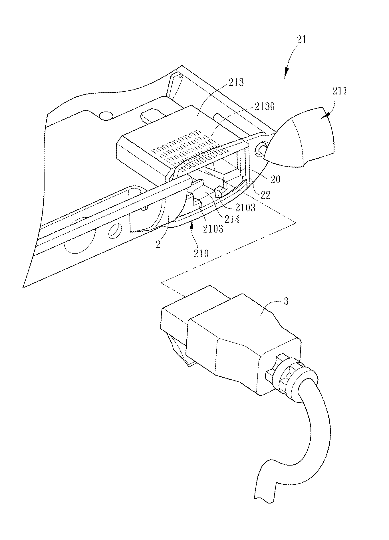
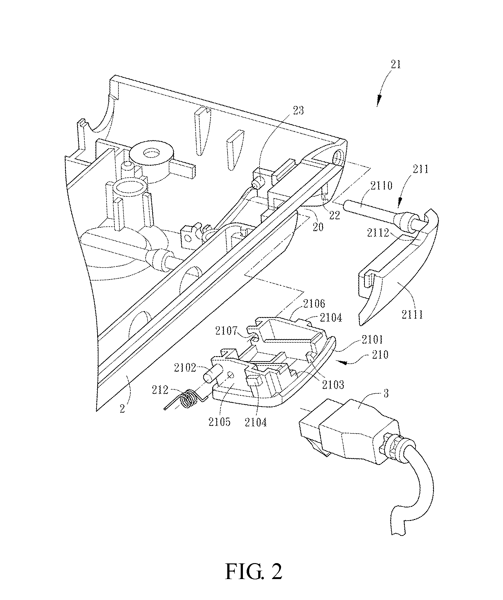
[0021]FIG. 2 is an exploded schematic diagram showing a connector socket according to one preferred embodiment of the invention. FIG. 3 is an assembled diagram showing a connector socket according to one preferred embodiment of the invention. Please refer to FIG. 2 and FIG. 3 together.

[0022]A connector socket 21 according to the embodiment is disposed at an opening 20 of a casing 2 for connecting a connector 3. In the embodiment, the connector socket 21 includes a rotatable element 210, a covering element 211, and an elastic element 212.

[0023]In FIG. 2, the rotatable element 210 has a protrudent portion 2101, a connecting shaft 2102, a fastening portion 2103, a first blocking portion 2104, and side walls 2105 and 2106.

[0024]In the embodiment, the protrudent portion 2101 is disposed at an outer edge of the rotatable element 210. In the embodiment, the rotatable element 210 is disposed at the lower side of the opening 20, and the protrudent portion 2101 can be disposed to protrude upw...


PUM


Abstract

This invention provides a connector socket and a portable electronic device using the same. The connector socket is disposed at a casing for connecting a connector. The connector socket includes a rotatable element and an elastic element. The rotatable element is pivotally connected to the casing. The elastic element is coupled to the casing and the rotatable element. The rotatable element has a protrudent portion. When the connector is connected to the connector socket, the connector presses the protrudent portion to allow the rotatable element to automatically rotate from a storage position to an open position. When the connector is separated from the connector socket, the rotatable element automatically rotates from the open position to the storage position via the elastic element.

Description

[0001]This Non-provisional application claims priority under 35 U.S.C. §119(a) on Patent Application No(s). 098109732 filed in Taiwan, Republic of China on Mar. 25, 2009, the entire contents of which are hereby incorporated by reference.BACKGROUND OF THE INVENTION[0002]1. Field of the Invention[0003]This invention relates to a connector socket and, more particularly, to a connector socket and a portable electronic device using the same.[0004]2. Description of the Related Art[0005]With development of electronic technology, electronic devices with small volume and powerful functions attract more and more users. The electronic devices usually need signal cables for transferring power, data and so on. The signal cables are usually connected to the electronic devices by connectors. Therefore, connector sockets cooperating with the connectors are generally applied to the electronic devices. For example, an RJ45 connector socket for a network node is usually applied.[0006]However, since th...

Claims


Application Information

Patent Timeline
Patent Type & Authority Applications(United States)
IPC IPC(8): H01R24/00
CPCH01R13/447H01R24/64H01R2201/06H01R13/5213
Inventor HUNG, SHIH-WEIYE, XIAO
Owner PEGATRON
Why Eureka
Try Eureka