Method and device for synchronization and channel estimation in a radio receiver

a radio receiver and channel estimation technology, applied in the field of radio telecommunication systems, can solve the problems of no longer producing an accurate synchronization position or channel estimation, and the effect of affecting the synchronization position and channel estimation of the receiver

Active Publication Date: 2010-09-30
TELEFON AB LM ERICSSON (PUBL)
View PDF4 Cites 33 Cited by
  • Summary
  • Abstract
  • Description
  • Claims
  • Application Information

AI Technical Summary

Benefits of technology

[0011]In another embodiment, the present invention generates an initial channel estimate based on the spatially and temporally stacked signal model; finds a synchronization position for the received signal based on the initial channel estimate; computes a whitening filter based on the initial channel estimate and the synchronization position; generates a whitened signal and a whitened training sequence based on the computed whitening filter; and computes an improved channel estimate based on the whitened signal and whitened training sequence.

Problems solved by technology

As a result, mutual interference among users occupying the same radio channel has become a major source of signal disturbance.
When spatial / temporal whitening is performed during equalization or demodulation, the operating carrier-to-interference power ratio (C / I) can be changed so drastically that the ordinary method of synchronization and channel estimation, such as the least-squares (LS) method, can no longer produce an accurate synchronization position or channel estimate.
As a result, the reliability of synchronization and channel estimation becomes a bottleneck of the overall receiver performance.
These methods do not exploit the convolutional structure of the whitened channel, and thus attempt to estimate more unknown parameters than is needed.
As a result, the quality of the channel estimate suffers.

Method used


Image

  • Method and device for synchronization and channel estimation in a radio receiver
  • Method and device for synchronization and channel estimation in a radio receiver
  • Method and device for synchronization and channel estimation in a radio receiver

Examples


first embodiment

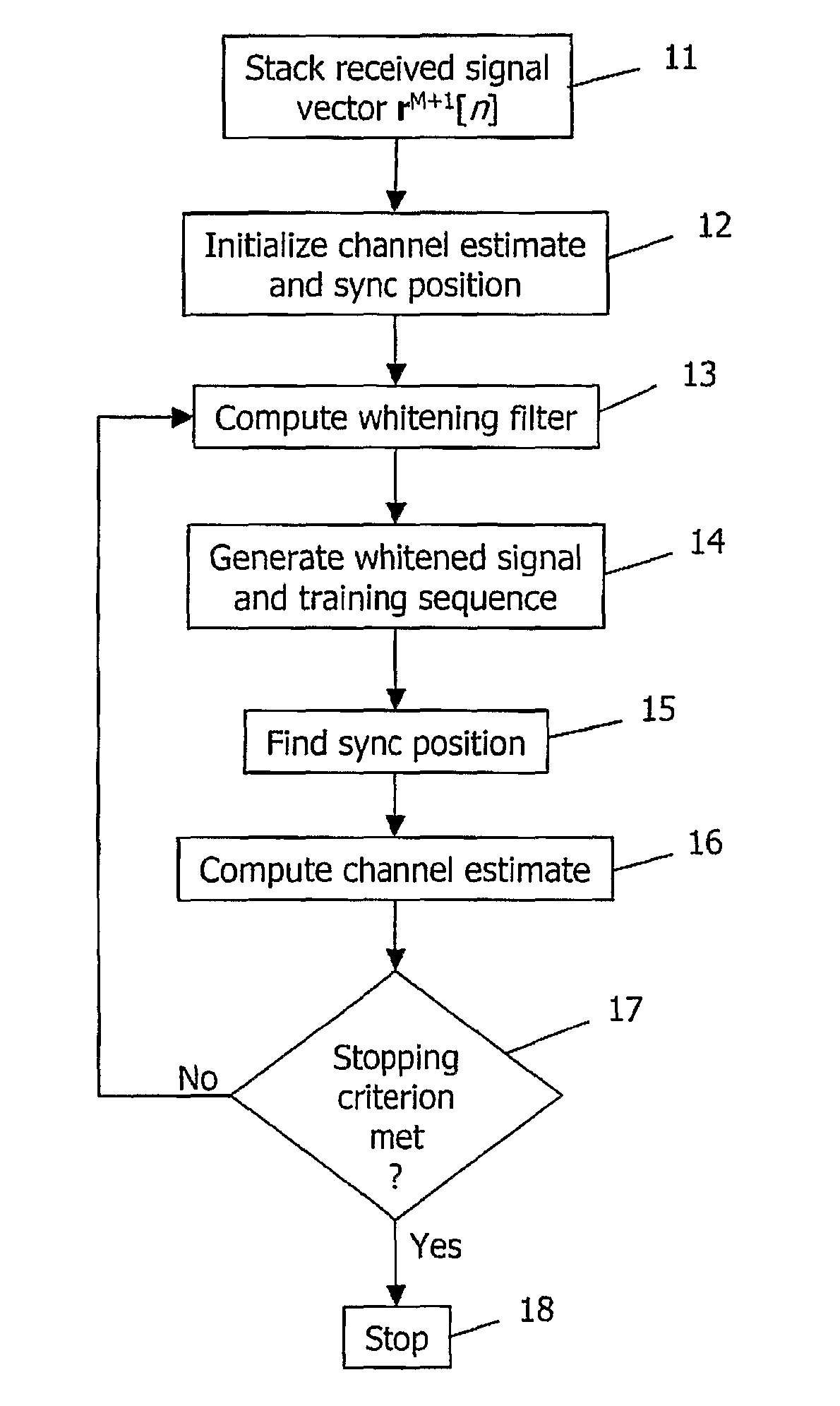
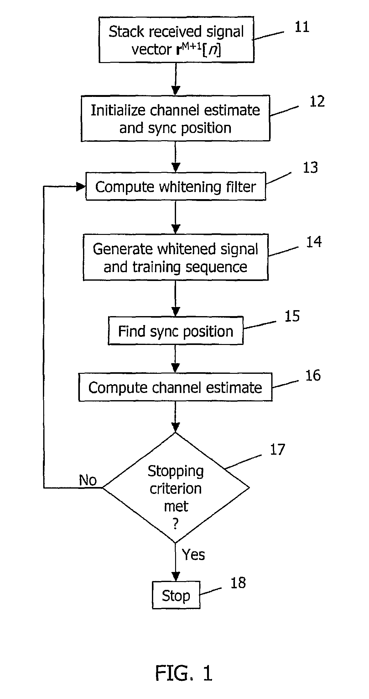
[0029]FIG. 1 is a flow chart of the method of the present invention in which the order of iteration F→n0→C is utilized. In this embodiment, the iteration starts with an initial estimate of C and n0, followed by a first computation of the whitening filter F. At step 11, a stacked received signal vector rM+1[n] is generated. At step 12, the channel estimate C and the synchronization position n0 are initialized. At step 13, the whitening filter {circumflex over (F)} is computed in a first iteration based on the fixed values of the channel estimate C and the synchronization position n0. In the preferred embodiment, the whitening filter estimate {circumflex over (F)} is computed as the “square root” of the inverse of the matrix:

Λ^≡∑n=L+M-1N-1(rM+1[n+n^0]-T(C^)sL+M[n])(rM+1[n+n^0]-T(C^)sL+M[n])H(1)

such that {circumflex over (F)}H{circumflex over (F)}={circumflex over (Λ)}−1, where:

T(C)≡[C[0]C[1]…C[L-1]0…00C[0]C[1]…C[L-1]0⋮⋮⋮⋮⋮⋮⋮⋮⋮0C[0]C[1]…C[L-1]00…0C[0]C[1]…C[L-1]](2)

is an (M+1)×(L+M) bl...

second embodiment

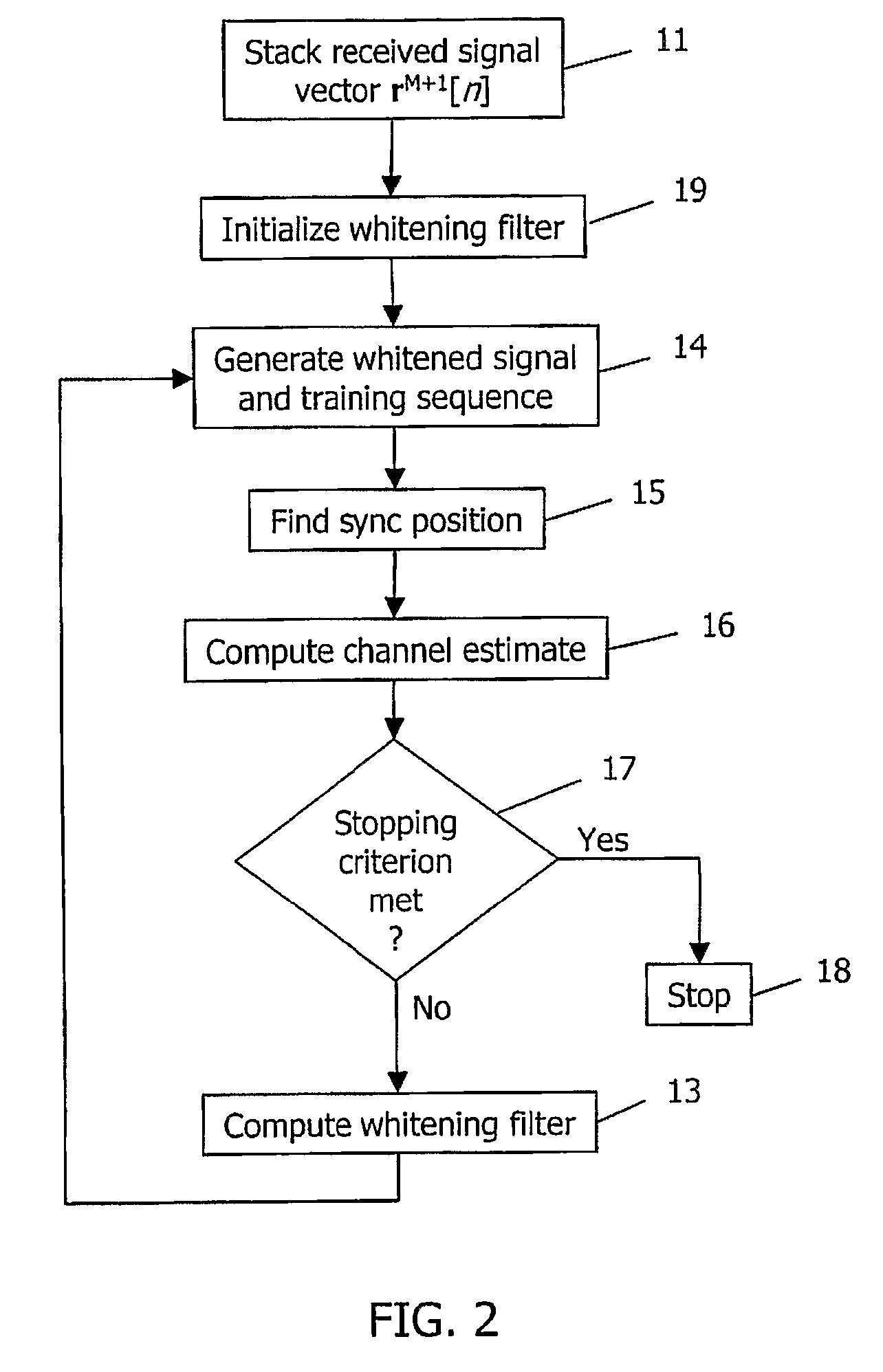
[0037]FIG. 2 is a flow chart of the method of the present invention in which the order of iteration F→n0→C is utilized. Similar steps are numbered the same in all figures. In this embodiment, the iteration starts with an initial estimate of the whitening filter F, followed by a first computation of the synchronization position n0 and the channel estimate C. At step 11, a stacked received signal vector rM+1[n] is generated. At step 19, the whitening filter is initialized. At step 14, a whitened received signal ŷ[n] and whitened training symbol {circumflex over (t)}[n] are generated using the procedures described above. At step 15, the synchronization position n0 is found based on the whitened signal ŷ[n] and whitened training symbol {circumflex over (t)}[n]. At step 16, the channel estimate Ĉ is computed for the found synchronization position {circumflex over (n)}0 based on the whitened signal ŷ[n] and whitened training sequence {circumflex over (t)}[n].

[0038]At step 17, it is determ...

third embodiment

[0039]FIG. 3 is a flow chart of the method of the present invention in which the order of iteration F→n0→C is utilized. Again, similar steps are numbered the same in all figures. In this embodiment, the iteration starts with an initial estimate of C and n0, followed by a first computation of the whitening filter F. At step 11, a stacked received signal vector rM+1[n] is generated. At step 12, the channel estimate C and the synchronization position n0 are initialized. At step 13, the whitening filter {circumflex over (F)} is computed in a first iteration based on the fixed values of the channel estimate C and the synchronization position n0.

[0040]At step 17, it is determined whether a predefined stopping criterion has been met. Once again, the stopping criterion may be based on a predefined fixed number of iterations, or a determination that the percentage change in a quantity, such as the channel estimation error, E(Ĉ,{circumflex over (Λ)},{circumflex over (n)}0), or the log likelih...


PUM


Abstract

A device and method in a radio receiver for generating synchronization and channel estimation information based on three parameters consisting of a synchronization position, at least one whitening filter parameter, and a channel estimate. A spatially and temporally stacked signal model is generated by stacking successive samples of temporally adjacent received signal vectors and corresponding training vectors. Initial estimates of a first one or two of the three parameters are then generated based on the spatially and temporally stacked signal model. The rest of the three parameters are then computed based on the initial estimates of the first one or two parameters. If a stopping criterion is met, the method ends and the parameters are used to process the signal. If the stopping criterion is not met, additional iterations are performed to improve the synchronization and estimation information.

Description

FIELD OF THE INVENTION[0001]The present invention relates to radio telecommunication systems. More particularly, and not by way of limitation, the present invention is directed to a method and device in a radio receiver for generating synchronization and channel estimation information with adaptive spatial / temporal whitening.BACKGROUND OF THE INVENTION[0002]The increasing popularity of mobile communications has placed a tremendous demand on the scarce radio resources of cellular communication networks. To efficiently utilize these valuable resources, radio frequencies in Time Division Multiple Access (TDMA) cellular systems such as GSM / EDGE, are being reused with closer proximity than ever. As a result, mutual interference among users occupying the same radio channel has become a major source of signal disturbance. The ability to suppress co-channel interference has become increasingly important for mobile receivers in cellular systems with tight reuse.[0003]Multi-branch diversity o...

Claims


Application Information

Patent Timeline
Patent Type & Authority Applications(United States)
IPC IPC(8): H04B1/16
CPCH04L25/0224H04L25/0212
Inventor HUI, DENNISHAFEEZ, ABDULRAUF
Owner TELEFON AB LM ERICSSON (PUBL)
Why Eureka
Try Eureka