Modular necks for orthopaedic devices

a technology of orthopaedic devices and modules, applied in the field of orthopaedic implants, can solve the problems of increasing the risk of fracture, and increasing the risk of surgery,

Inactive Publication Date: 2010-09-30
SMITH & NEPHEW INC
View PDF67 Cites 32 Cited by
  • Summary
  • Abstract
  • Description
  • Claims
  • Application Information

AI Technical Summary

Benefits of technology

[0014]According to one aspect of the invention, there is provided a system of modular orthopaedic devices. The system comprises one or more hip implants or trials, each hip implant or trial having a femoral stem and one of at least two neck segments having different geometries. Each neck segment comprises a proximal end configured to receive a femoral head portion and a distal end configured to be operably received by a proximal portion of the femoral stem. Each proximal end comprises a central portion generally representative of a femoral head center. When each of the at least two neck segments are joined with the femoral stem, the central portion is displaced a predetermined distance in a single direction relative to the femoral stem. The neck segments provided, therefore, advantageously allow a user to independently adjust any one of a height, an offset, or a version angle of an orthopaedic device for best performance and fit.
[0015]According to yet another aspect of the invention, there is provided a kit of modular neck segments. The kit allows a surgeon to fine-tune leg length independently of offset and / or version angle.
[0016]According to yet even another aspect of the invention, there is provided a kit of modular neck segments. The kit allows a surgeon to fine-tune implant offset independently of overall implant height and / or version angle.
[0017]According to another aspect of the invention, there is provided a kit of modular neck segments. The kit allows a surgeon to fine-tune version angle independently of implant offset and / or overall implant height.

Problems solved by technology

This problem may cause the patient to have too short or too long of a leg.
This increases the risk of fracture and is more invasive, because precious cortical bone is removed to make room for the prosthesis.
However, there are several problems with these prior designs.
For example, the junction between the proximal body and the distal stem forms a stress riser at a central portion of the implant, making the implant more vulnerable to fatigue and shear under loading.
Many of these modular prior art devices are susceptible to fatigue failure.
Moreover, these prior implants can be difficult to assemble because the junction is usually located inside the femoral canal and cannot be easily seen.
Lastly, each junction is subject to contamination by bone debris, blood, or other biological matter that could potentially prevent or interfere with establishing a good taper lock at the junction, further increasing the risk of implant failure.
This method disadvantageously changes offset and / or version angle simultaneously with height, because of the way the sine and cosine components of the neck change with changes in neck length (i.e., the hypotenuse) and angle.
In an operating room, it can become quite tedious and confusing to keep track of what geometries are changing between neck segment selections during trial reduction.
Due to the complex and iterative nature of changing more than one input variable at a time, it is difficult for a surgeon to re-establish the proper joint stability when using modular necks of the prior art, if leg length needs to be adjusted.
The problem with using such monolithic stems is that a surgeon needs to extract the entire implant from the medullary canal and replace it with another implant in order to change the overall implant height.
Each time an implant is inserted and extracted from a medullary canal, there is trauma to the bone and surrounding soft tissues (e.g., increased risk of fat embolism and / or fracture).
Moreover, each time an implant is inserted and extracted from a medullary canal, there may be a loss of bone fixation or stability.
Furthermore, each time an implant is inserted and extracted from a medullary canal, rotation needs to be re-set and there is no guarantee that the height will be optimal when the implant is fully re-seated in the canal.

Method used


Image

  • Modular necks for orthopaedic devices
  • Modular necks for orthopaedic devices
  • Modular necks for orthopaedic devices

Examples


Embodiment Construction

[0031]The following description of the preferred embodiment(s) is merely exemplary in nature and is in no way intended to limit the invention, its application, or uses.

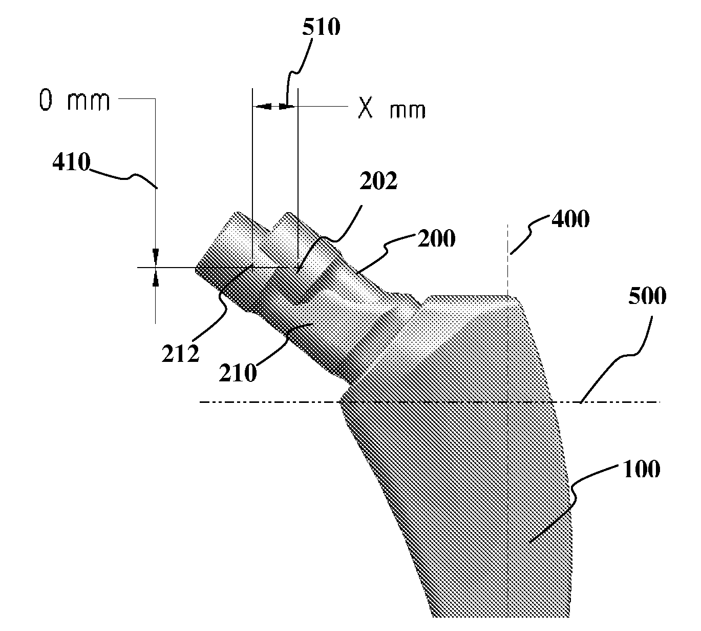
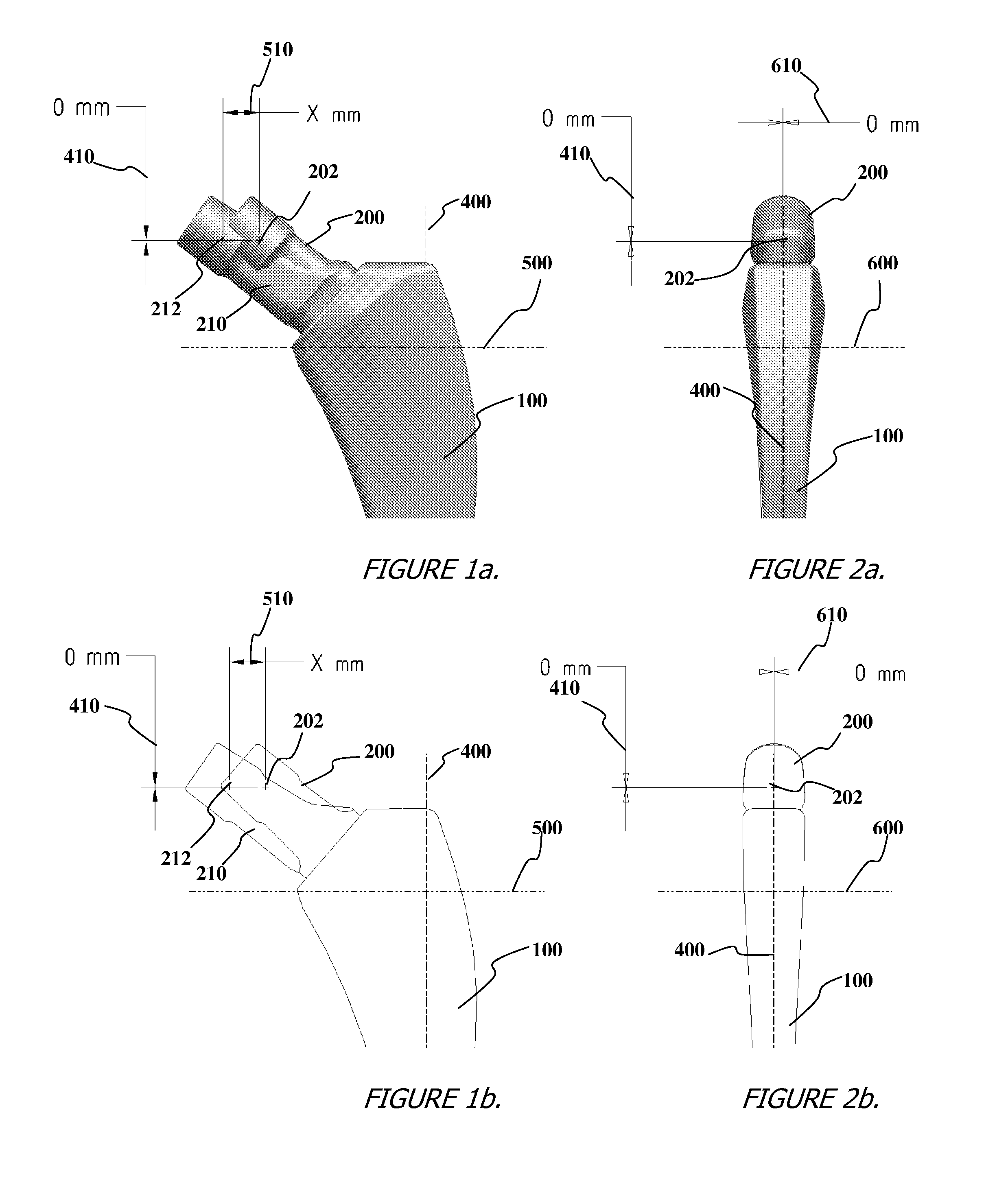
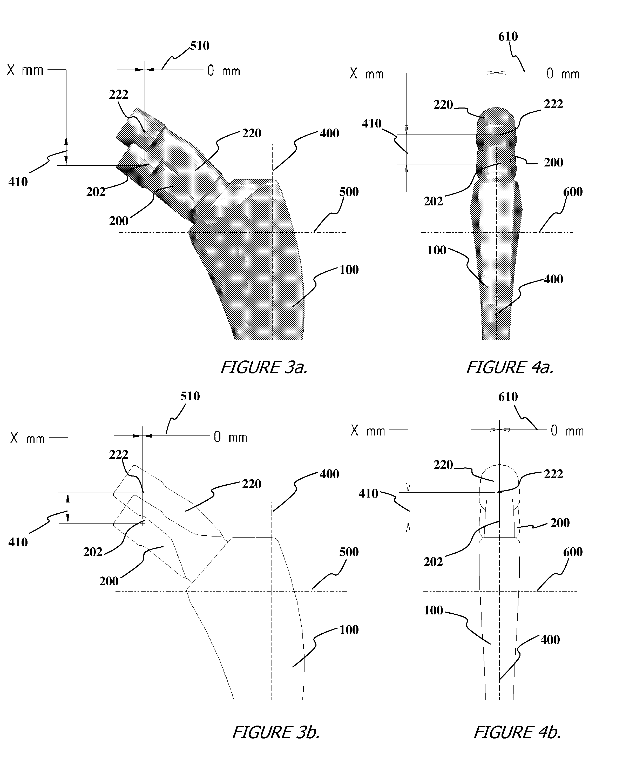
[0032]Referring to the accompanying drawings, FIGS. 1a-2b illustrate a system of modular orthopaedic devices according to some embodiments. The system comprises a femoral stem (100) and one of at least two neck segments (200, 210). The neck segments (200, 210) generally have a proximal end configured to receive a femoral head implant (not shown), and a distal end configured to be operably received by the femoral stem (100). The junction between the neck segments (200, 210) may be any known in the art, but is preferably a Morse taper lock. The proximal end of each neck comprises a central portion (202, 212) which is representative of the femoral head center when each of a femoral stem (100), neck (200), and femoral head implant (not shown) are assembled together.

[0033]One of said at least two neck segments may be a sta...


PUM


Abstract

There is provided a system of modular orthopaedic devices. The system comprises one or more hip implants or trials, each hip implant or trial having a femoral stem and one of at least two neck segments having different geometries. Each neck segment comprises a proximal end configured to receive a femoral head portion and a distal end configured to be operably received by a proximal portion of the femoral stem. Each proximal end comprises a central portion generally representative of a femoral head center. When each of the at least two neck segments are joined with the femoral stem, the central portion is displaced a predetermined distance in a single direction relative to the femoral stem. The neck segments provided, therefore, advantageously allow a user to independently adjust any one of a height, an offset, or a version angle of an orthopaedic device for best performance and fit.

Description

CROSS-REFERENCE TO RELATED APPLICATIONS[0001]This application claims the benefit of U.S. Provisional Application No. 60 / 976,717, filed Oct. 1, 2007 and U.S. Provisional Application No. 60 / 976,697, filed Oct. 1, 2007. The disclosure of each application is incorporated by reference in its entirety.STATEMENT REGARDING FEDERALLY SPONSORED RESEARCH[0002]N / ABACKGROUND OF THE INVENTION[0003]1. Field of the Invention[0004]The present invention relates generally to orthopaedic implants, and more particularly to modular femoral implants for use in hip arthroplasty.[0005]2. Related Art[0006]In some instances, an implant may sit higher or lower than anticipated after its insertion into a medullary canal of a bone. For example, in hip arthroplasty, a femoral stem portion of a hip prosthesis may seat proximally proud, or might otherwise seat more distally than expected after it is inserted into a prepared femoral canal. This problem may cause the patient to have too short or too long of a leg.[00...

Claims


Application Information

Patent Timeline
Patent Type & Authority Applications(United States)
IPC IPC(8): A61F2/32
CPCA61F2/0095A61F2/3609A61F2/40A61F2/4684A61F2002/30604A61B17/1668A61F2002/3071A61F2002/3625A61F2250/0085A61B17/164A61F2002/30616
Inventor BERGIN, ALISHA W.JONES, JERRY L.LAMBERT, RICHARD D.
Owner SMITH & NEPHEW INC
Why Eureka
Try Eureka