Shim

Inactive Publication Date: 2010-10-07
LOUVER LITE
View PDF9 Cites 19 Cited by
  • Summary
  • Abstract
  • Description
  • Claims
  • Application Information

AI Technical Summary

Benefits of technology

[0006]According to a first aspect of the invention, there is provided a shim for reducing play between a roller blind tube and a roller blind end plug, the shim including a rib receiving portion sized and configured to receive a rib from a roller blind tube, wherein the shim is capable of being located between adjacent splines of a roller blind end plug.
[0007]The shim according to the invention therefore fills the gap between the roller tube ribs(s) and the splines of the end plugs, which reduces or substantially eliminates the rotational play between the two components.

Problems solved by technology

However, where two or more blinds are located adjacent to each other and coupled such that both are operated simultaneously from a single control mechanism, the play between the end plugs and the roller tube may cause problems.
This combined play between the tubes and the end plugs can translate to a linear mismatch between the blinds in use, which is not desired by the user.

Method used


Image

  • Shim
  • Shim
  • Shim

Examples


second embodiment

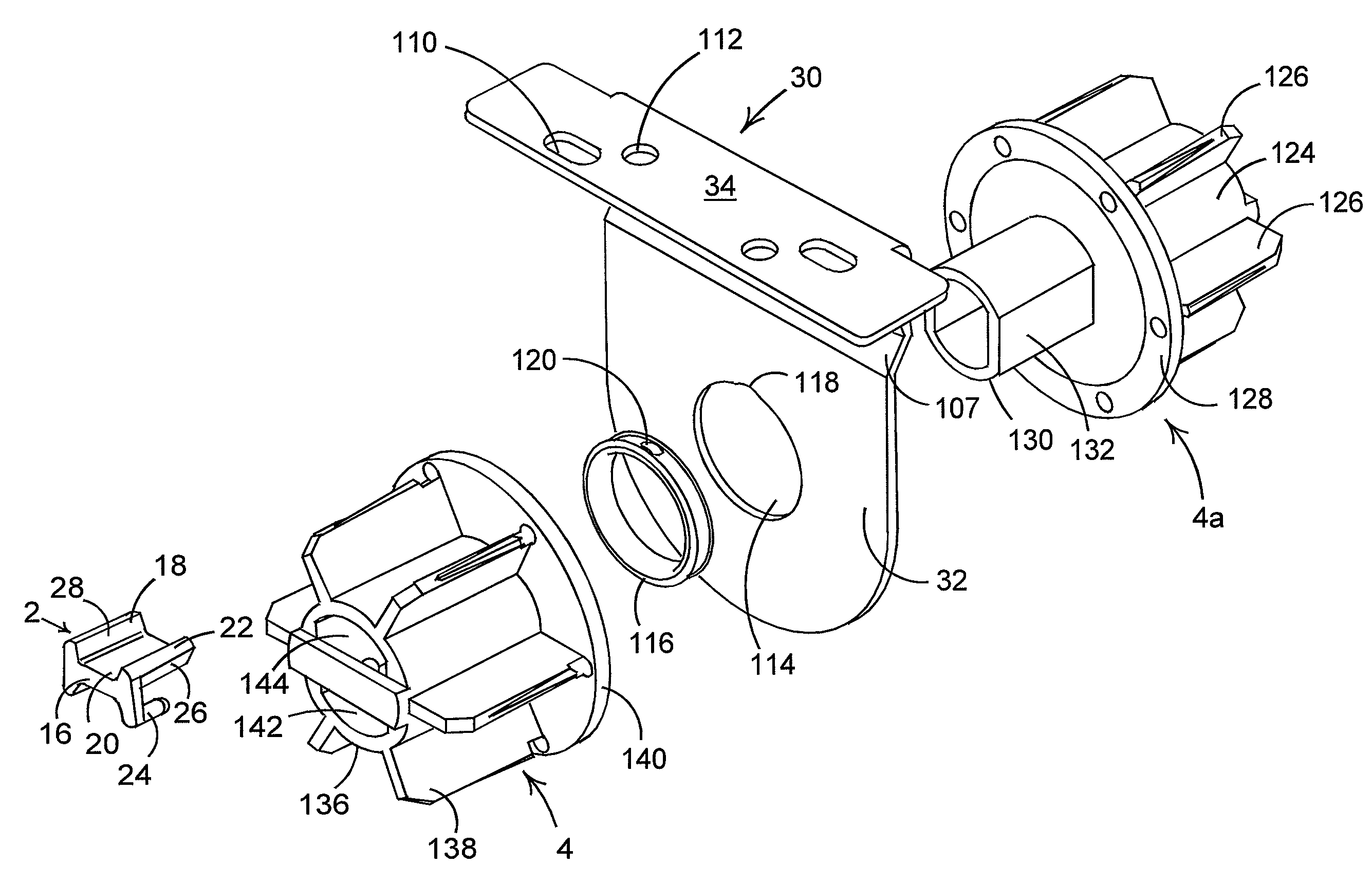
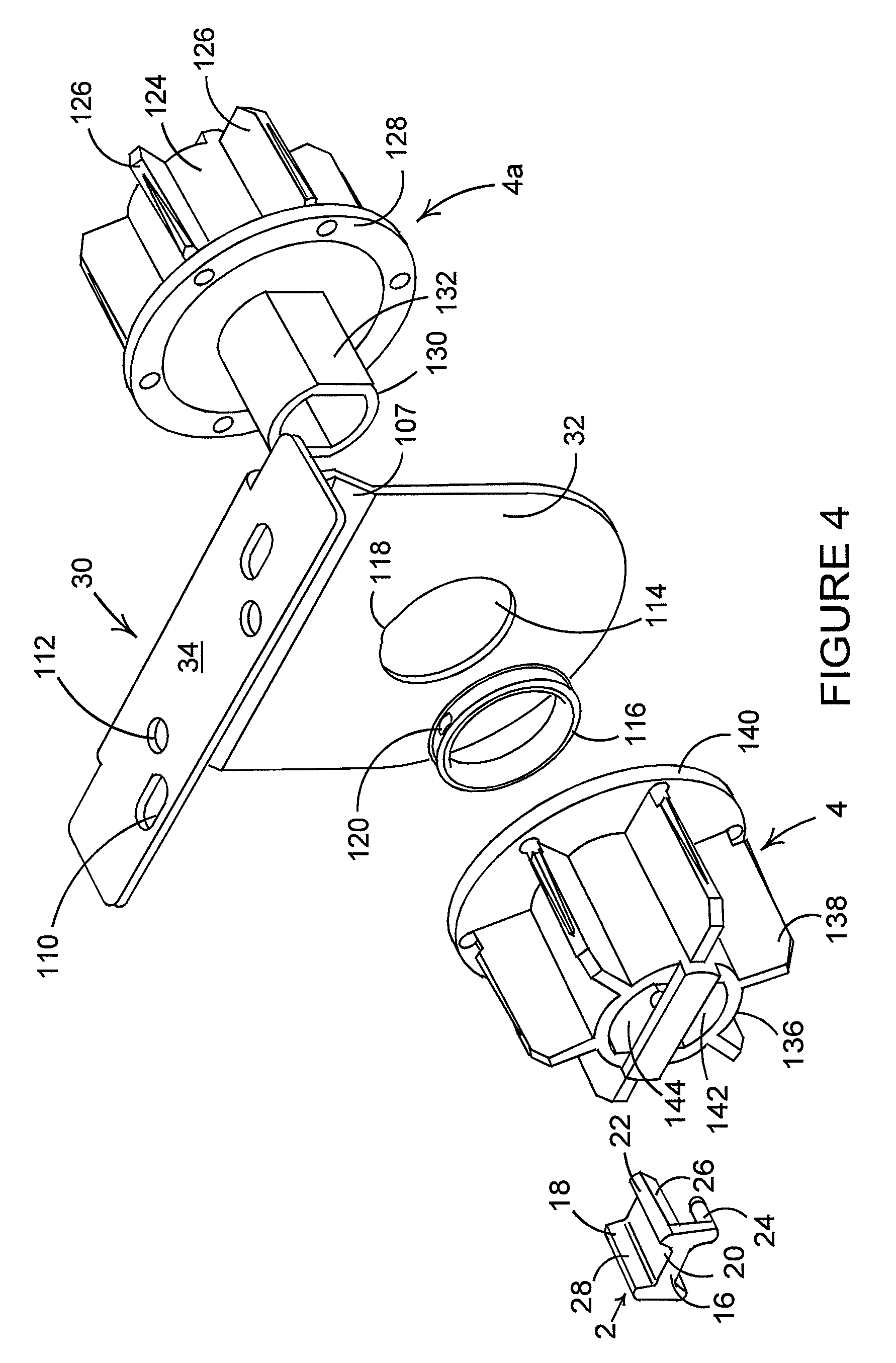
[0067]FIG. 4 shows a blind linkage according to the invention as an exploded view. The linkage includes the common support bracket 30 which consists of the mounting element 34, including holes 110, 112 formed therein through which screws or other fixings may pass in order to secure the bracket 30 to a suitable surface, such as a wall or ceiling. Depending downwardly (as shown in FIG. 4) from the mounting element 34 is the support element 32. A portion 107 of the support element 32 is angled such that the main section of the support element 32 defines a plane which approximately bisects the mounting element 34 along its longitudinal axis. The support element 32 is formed from a metal such as aluminium or steel.

[0068]The support element 32 defines therein an aperture 114 which is substantially circular in cross section. Located around the circumference of the aperture 114 is a bush 116 formed of a polymeric material, such as nylon. The bush 116 includes a lug 120 which is configured t...

third embodiment

[0082]the invention is provided by an alternative first end plug 4b which is shown in FIG. 5.

[0083]In this embodiment, the alternative first end plug 4b is substantially identical to the first end plug 4 of the second embodiment, except for the channel defined therein.

[0084]Thus, the alternative first end plug 4b includes a body 236 which has six splines 238 extending radially therefrom. As with the second embodiment, the body 236 terminates at one end in an end plate 240, which is of circular cross section. However, instead of a channel including a pair of opposed flats, the body 236 and the end plate 240 of the alternative first end plug 4b define a channel 250 having a circular cross section.

[0085]The diameter of the channel 250 is substantially identical to the diameter of the channel 142 of the second embodiment. However, the absence of the flats in the channel 250 allows the shaft 130 to rotate freely within the channel 250.

[0086]The skilled person will appreciate that althoug...


PUM


Abstract

A shim for reducing play between a roller blind tube and a roller blind end plug, the shim including a rib receiving portion sized and configured to receive a rib from a roller blind tube, wherein the shim is capable of being located between adjacent splines of a roller blind end plug.

Description

TECHNICAL FIELD[0001]The present invention relates to a shim for reducing play between a roller blind tube and a roller blind end plug. In particular, the shim may be used in conjunction with a blind linkage suitable for linking together two adjacent blinds.BACKGROUND[0002]In conventional roller blinds, a roller tube is mounted between a pair of roller blind end plugs. This is typically achieved by providing the end plugs with a number of splines or fins which in use are located within the roller blind tube. In order to rotationally couple the roller blind tube to the end plugs, the roller blind tube typically includes one or more radially inwardly projecting ribs which extend along the entire length of the tube. The rib or ribs are circumferentially spaced such that they sit between a pair of adjacent splines of the two end plugs. However, the ribs tend to smaller than the gap defined between the adjacent splines. This results in the roller tube being able to rotate by a small amou...

Claims


Application Information

Patent Timeline
IPC IPC(8): E06B9/44E21B19/16
CPCY10T403/40E06B9/50
Inventor BARNES, ANTONYGREENING, ANDREW
Owner LOUVER LITE
Why Eureka
Try Eureka