Two-axle drive system

Inactive Publication Date: 2009-05-28
SIEMENS GEARED MOTORS
View PDF6 Cites 9 Cited by
  • Summary
  • Abstract
  • Description
  • Claims
  • Application Information

AI Technical Summary

Benefits of technology

[0015]In a particularly preferred embodiment of the present invention, it may be provided that the at least one gear unit, and preferably each gear unit, includes a first and second worm gear stage, thereby resulting in self-locking. Due to the self-locking, a specified position may be retained exactly. The position may be retained without the need for additional braking. Both of the gear stages are preferably in

Problems solved by technology

These surfaces must track the position of the sun with high accuracy, sin

Method used


Image

  • Two-axle drive system
  • Two-axle drive system
  • Two-axle drive system

Examples


Embodiment Construction

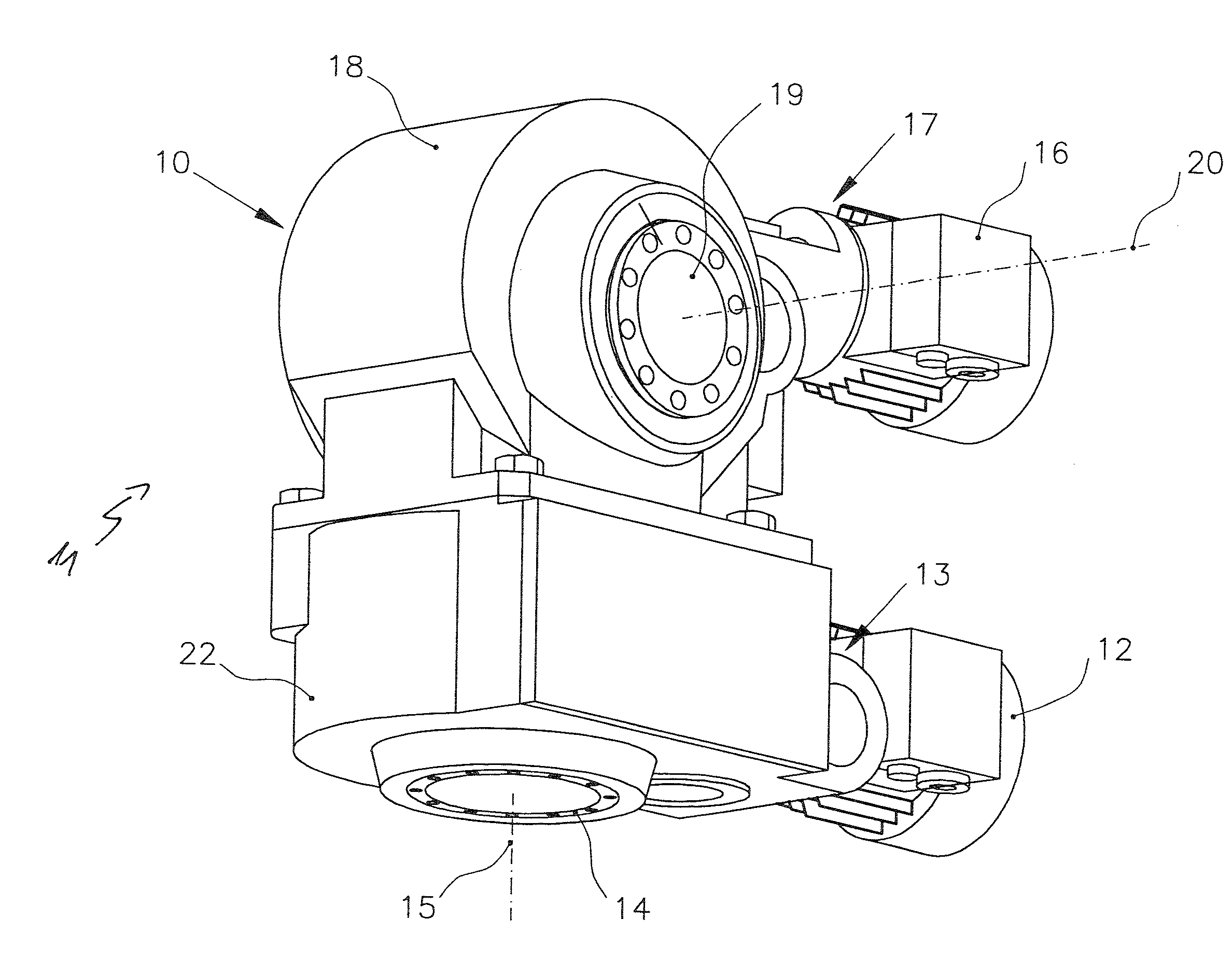
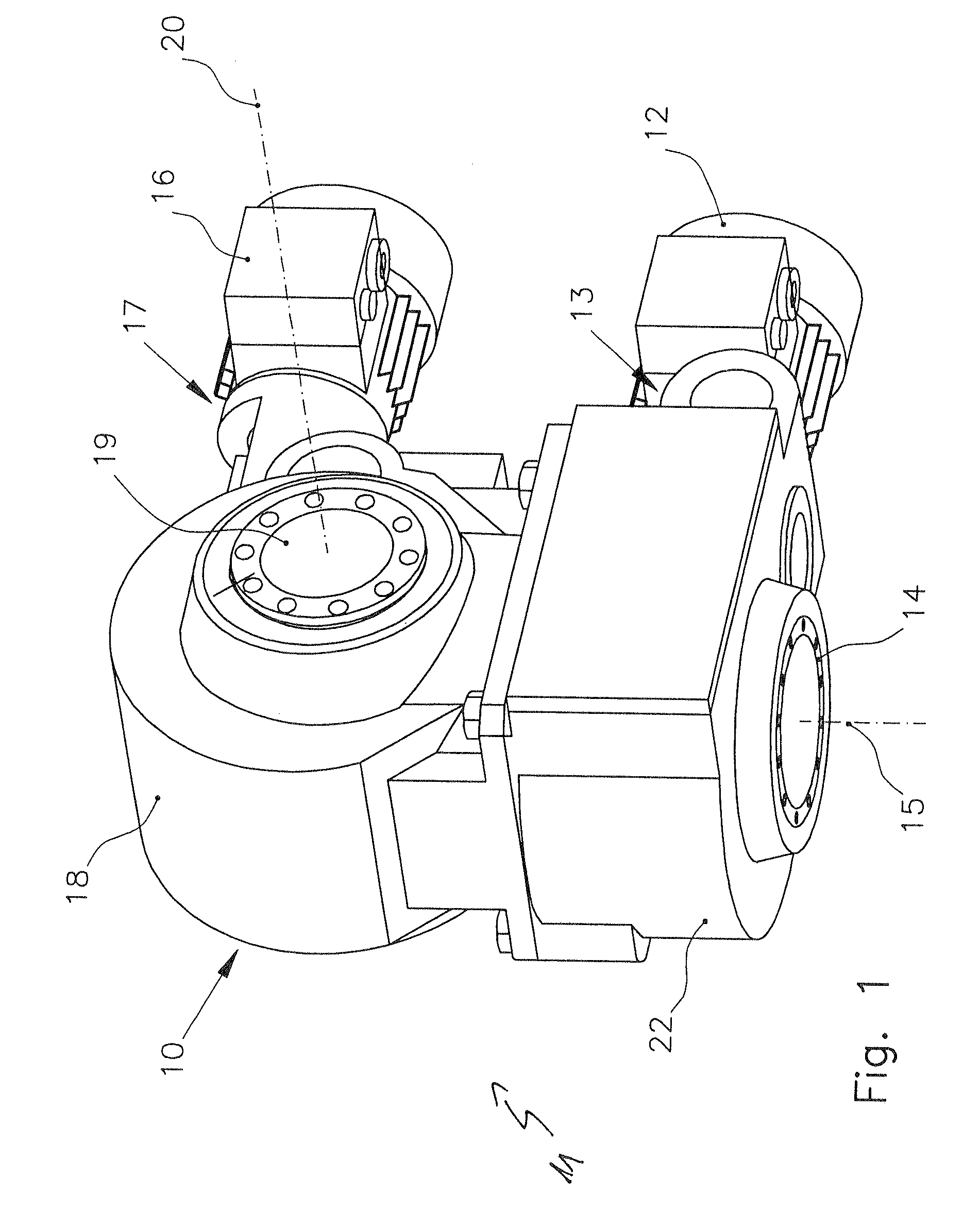
[0026]Housing 10 of two-axle drive system 11 is shown in FIG. 1. Drive 12, which is flange-mounted on a drive interface 13, drives a worm shaft of a first worm gear stage. In turn, this worm gear stage drives the worm shaft of a second worm gear stage, which, in turn, drives a shaft 14 via a spur gear stage. Since shaft 14 is non-rotatably situated, housing 10 may therefore be rotated about azimuth axis 15.

[0027]Drive 16 is also connected to a drive interface 17. It also drives two worm gear stages and a spur gear stage. Shaft 19 located in upper housing part 18 is driven as a result. Via drive 16, it is therefore possible to realize a rotational movement about elevation axis 20. Upper housing part 18 and lower housing part 22 are connected to each other via a threaded connection.

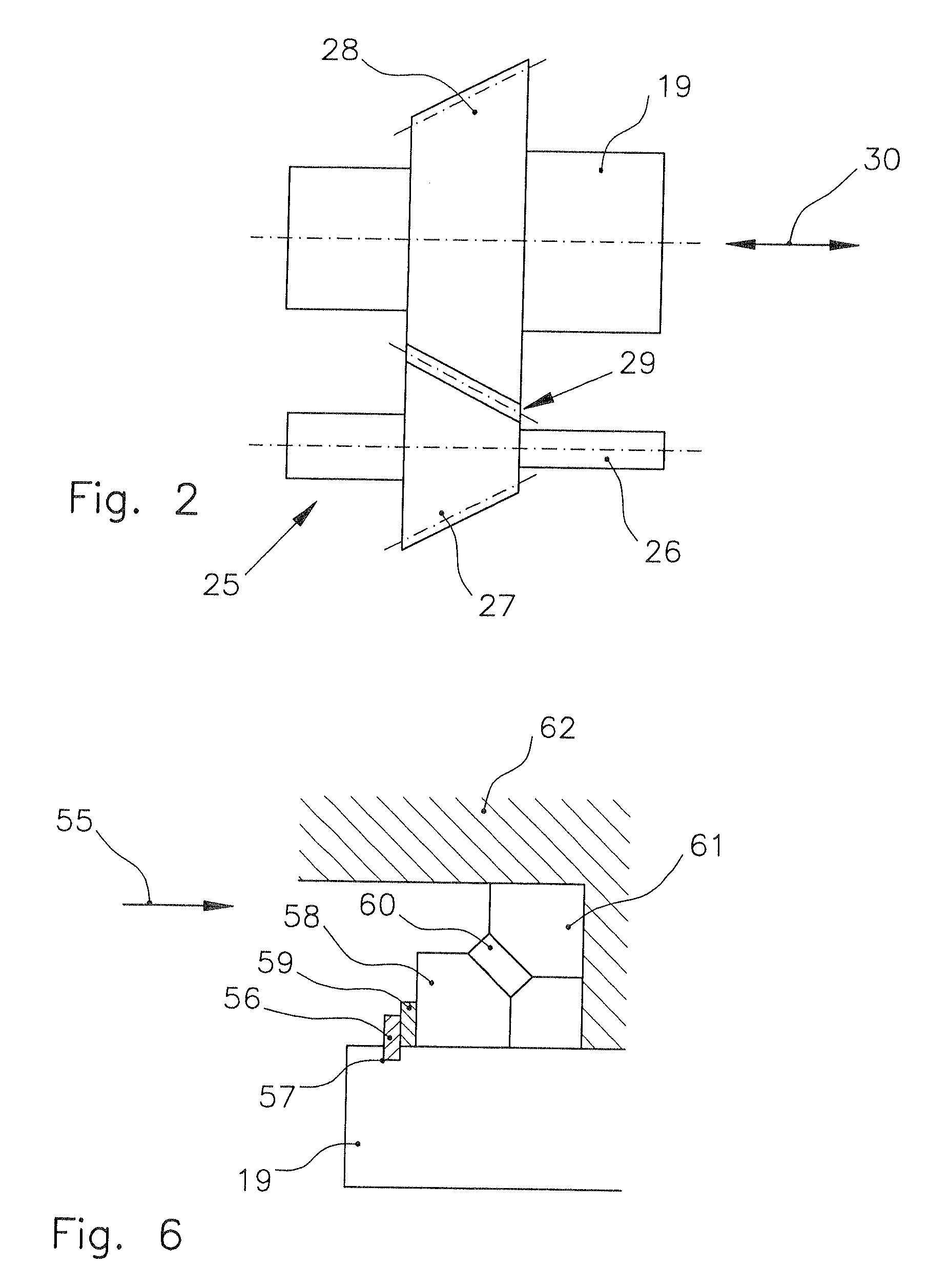
[0028]FIG. 2 shows a conical spur gear unit 25. Output shaft 26 of a worm gear stage and shaft 19 include conical spur gear toothing 27, 28. Tooth flank play 29 may be changed by moving shaft 19 in the dire...


PUM


Abstract

In a two-axle drive system for holding and moving large sunlight-absorbing, concentrating or reflecting surfaces about an azimuth axis and an elevation axis, a first gear unit which is driven by a first drive is provided for a rotational movement about the azimuth axis, and a second gear unit which is driven by a second drive is provided for a rotational movement about the elevation axis, at least one gear unit includes a spur gear stage with conical spur gear toothing, and the associated shaft is displaceable along its longitudinal axis. High accuracy is obtained as a result.

Description

CROSS-REFERENCE TO RELATED APPLICATION[0001]The invention described and claimed hereinbelow is also described in European Patent Application EP07022664.2 filed on Nov. 22, 2007. This European Patent Application, whose subject matter is incorporated here by reference, provides the basis for a claim of priority of invention under 35 U.S.C. 119(a)-(d).BACKGROUND OF THE INVENTION[0002]The present invention relates to a two-axle drive system for holding and moving sunlight-absorbing, concentrating or reflecting surfaces about an azimuth axis and an elevation axis, in the case of which a first gear unit which is driven by a first drive is provided for a rotational movement about the azimuth axis, and a second gear unit which is driven by a second drive is provided for a rotational movement about the elevation axis.[0003]Solar power plants operate according to different principles. Examples include parabolic trough power plants, tower power plants, and photovoltaic power plants. In all of ...

Claims


Application Information

Patent Timeline
IPC IPC(8): F16H37/16
CPCF16H1/06F16H1/206F16H2057/0221Y10T74/18024F24J2/5417F24J2002/5462Y02E10/47F16H2057/125F24S30/45F24S2030/134
Inventor KUNERT, JENSSCHNURR, WOLFGANGBOEING, GEORG
Owner SIEMENS GEARED MOTORS
Why Eureka
Try Eureka