
Inflatable Floating Beverage Cooler

Inactive Publication Date: 2010-10-07
CHURCHILL MARY LOUISE
View PDF17 Cites 31 Cited by
  • Summary
  • Abstract
  • Description
  • Claims
  • Application Information

AI Technical Summary

Benefits of technology

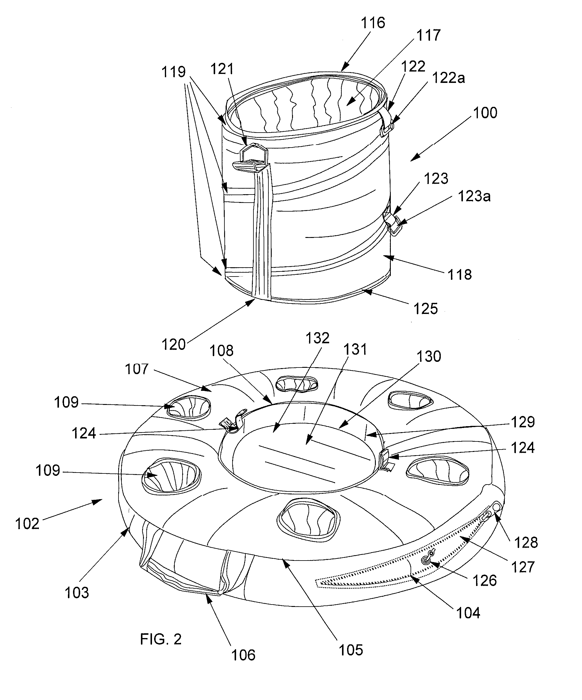
[0026]The invention also comprises storage means for easy carrying and compact storage of the container and flotation device. As described above, a preferred embodiment of the flotation device comprises a flexible sheet material covering substantially all of a flotation bladder. In this storage means embodiment, an underside of said covering bears a second layer of flexible material, the storage flap, secured to said underside by suitable means, such as by a zipper. In a set of steps to accomplish storage, the flotation device is deflated and the container is brought into a collapsed state and located in the container impression in the flotation device. Deflated and flexible portions of the flotation device are folded over the top of the container impression and the container. The storage flap is unzipped along a substantial part of its periphery, disengaging it from said underside of the covering material, and folded along a hinge connection to said underside so that what was an outside surface of the storage flap lies over the folded portions of the flotation device. The zipper of the storage flap is re-zipped to a closed position, thereby enclosing the folded down flotation device and container in a flattened disk, which may be easily stored. When the invention is in use, the positioning and configuration of the storage flap on the underside of the covering of the flotation device allow it to function as a ballast, thereby substantially stabilizing the invention and discouraging the flotation device from being inadvertently pushed by wind and / or currents.
[0028]Another objective is to provide such an apparatus that, in one embodiment, is capable of being quickly and easily moved from an open, erected state to a flattened, storable state by folding or compression and providing means to maintain said container in the flattened state.

Problems solved by technology

The expanded height is limited only by stability concerns.

Method used


Image

  • Inflatable Floating Beverage Cooler
  • Inflatable Floating Beverage Cooler
  • Inflatable Floating Beverage Cooler

Examples


Embodiment Construction

[0050]The above described drawing figures illustrate aspects of the invention in at least one of its exemplary embodiments, which are further defined in detail in the following description.

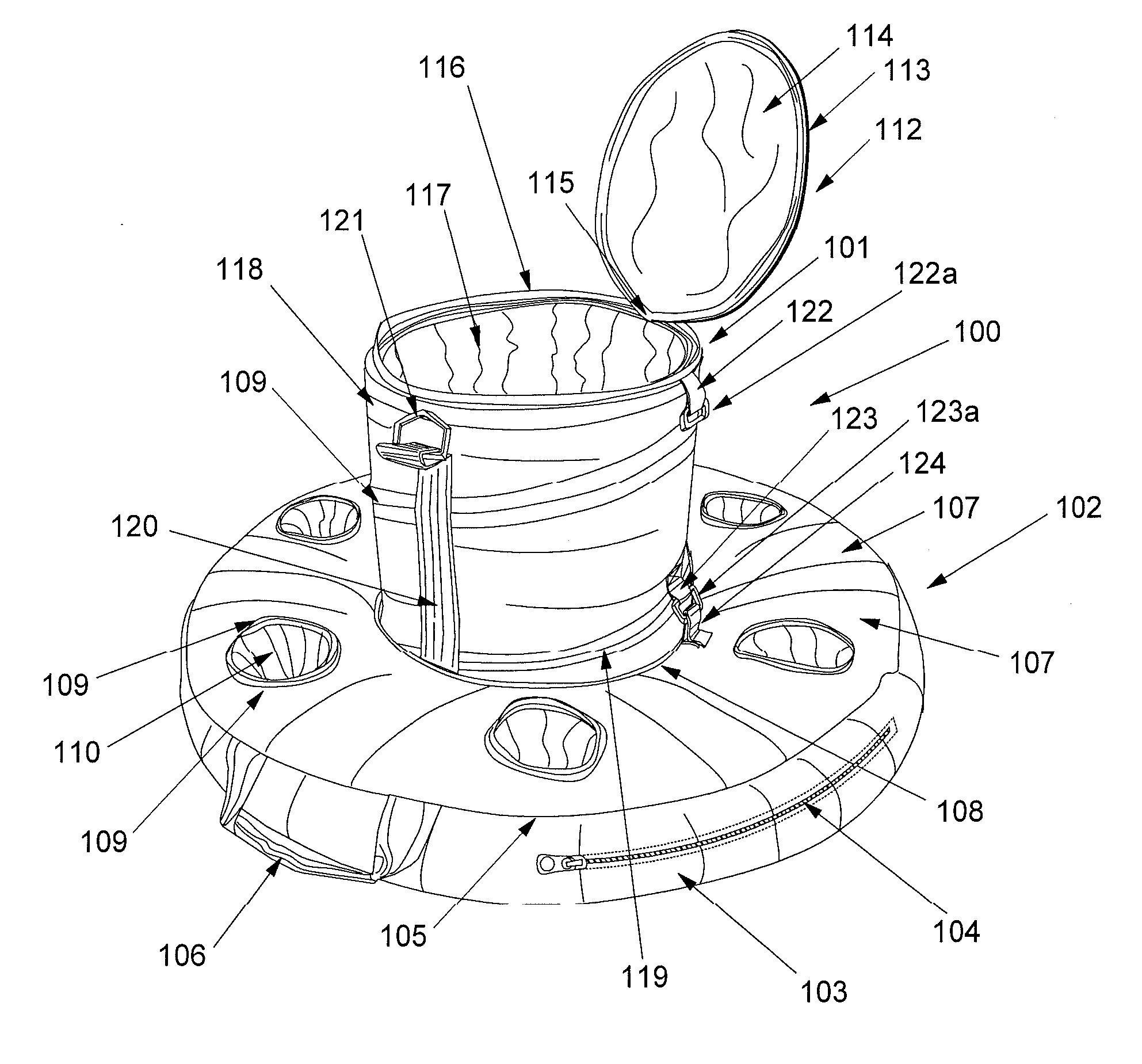
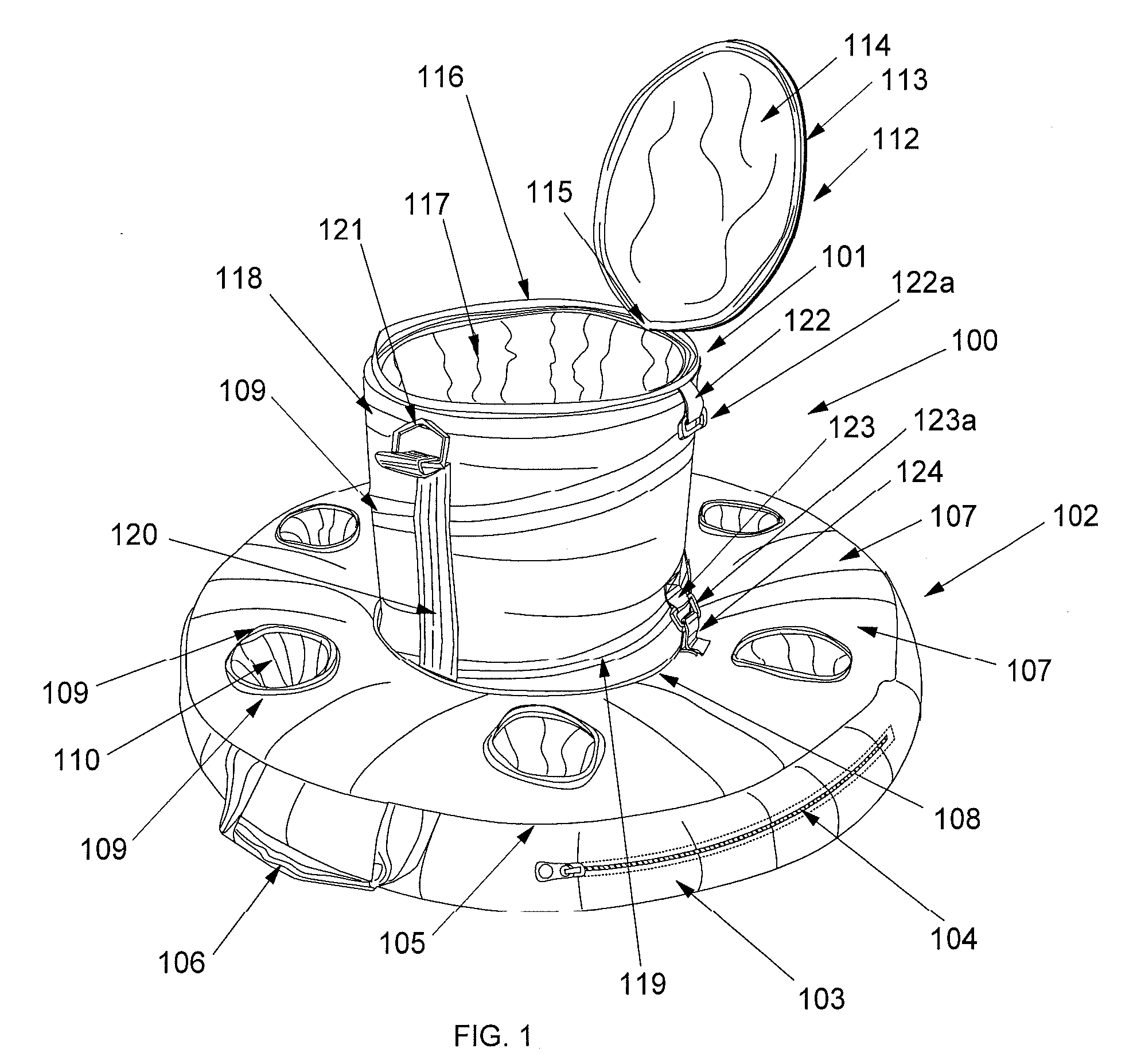
[0051]FIG. 1 is a perspective view of the invention assembly 100 comprising a collapsible beverage container 101 and flotation device 102, where said container 101 is, in the exemplary embodiment, releasably secured to a container impression in the flotation device 102. Flotation device 102 generally comprises a flotation bladder (not shown) bound with a protective cover 133, which comprises a outer side panel 103 and a top panel 107 connected by seam 105, which incorporates one of two lifting handles 106. Protective cover 133 is preferably formed from flexible sheet material such as woven nylon fabric or a similar material resistant to abrasion and repeated wetting. Outer side panel 103 comprises a zippered opening 104 for user access to the flotation bladder. Top panel 107 is interrupted by beve...


PUM


Abstract

A floating beverage cooler apparatus comprises, in an exemplary embodiment, a flotation bladder configured for removably receiving a beverage container. A protective cover is adapted to enclose and cover the flotation bladder and provides a bottom panel spanning an underside thereof. A storage flap is configured to be at least partially removably engaged substantially centrally with the bottom panel such that, when the apparatus is in use, a cavity is formed between the storage flap and bottom panel for providing added stability and resistance against lateral forces. When the apparatus is not being used, and the flotation bladder is deflated, the storage flap may be rotated about the protective cover and re-engaged with the bottom panel so that the storage flap lies over a top surface of the protective cover, thereby enclosing substantially all of the flotation bladder and protective cover, and optionally the beverage container, in a storage envelope.

Description

RELATED APPLICATIONS[0001]This is a continuation-in-part application of prior filed and currently pending U.S. non-provisional application Ser. No. 11 / 438,810, filed May 22, 2006, and entitled “Inflatable Cooler Flotation Device with Collapsible Cooler Container.” Furthermore, this application claims priority and is entitled to the filing date of the aforementioned application, the contents of which are incorporated by reference herein.INCORPORATION BY REFERENCE[0002]Applicant hereby incorporates herein by reference any and all U.S. patents and U.S. patent applications cited or referred to in this application.BACKGROUND OF THE INVENTION[0003]1. Field of the Invention[0004]The present invention relates to insulated containers for beverages and similar products which are collapsible for storage or carrying by a user. The invention further relates to said containers which are fixed in some manner to a flotation device.[0005]2. Description of Related Art[0006]The following art defines t...

Claims


Application Information

Patent Timeline
IPC IPC(8): B65D25/00B65D81/38
CPCA47G23/02A47G2200/02B63C9/30B63B38/00B63B22/24B63B35/00
Inventor CHURCHILL, ROBERT LEE
Owner CHURCHILL MARY LOUISE
Learn More