Real-time airborne particle analyzer

a particle analyzer and airborne technology, applied in the field of analytical instruments, can solve the problems of limiting the purity and composition of particles that may be analyzed effectively, preventing reliable real-time analysis of particles in an environment, and limiting the power of mass analysis, so as to reduce the electrical charge distribution and the speed of ablated particles

Inactive Publication Date: 2010-10-07
UT BATTELLE LLC
View PDF13 Cites 25 Cited by
  • Summary
  • Abstract
  • Description
  • Claims
  • Application Information

AI Technical Summary

Benefits of technology

[0007]In the present invention, an aerosol particle analyzer includes a laser ablation chamber, a gas-filled conduit, and a mass spectrometer. An aerosol particle supply system, which can employ, for example, an aerodynamic lens system, supplies aerosol particles into the laser ablation chamber The laser ablation chamber can be operated at a low pressure, which can be from 0.1 mTorr to 30 mTorr. The gas-filled conduit reduces the electrical charge distribution and the speed of ablated particles as the ablated particles collide with buffer gases in the gas-filled conduit. Preferably, the gas filled-conduit includes an electromagnetic multipole structure that collimates the ions ablated from the aerosol particles, which are guided into the mass spectrometer. Because the gas-filled conduit allows storage and statistical mixing of the enormous number of ions from the ablated particles, the measured ion distribution correlates with the elemental composition of the individual particle Ions from the same particle can be sampled from the large trap into the mass analyzer many times if desired.

Problems solved by technology

This is especially true when the particle has a non-homogeneous composition and morphology Additionally, the mass analysis can only be performed one time per laser ablation event.
Thus, the prior art instrumentation requires ablation of aerosol particles at an high vacuum environment, and thereby limits the purity and composition of particles that may be analyzed effectively.
Such a limitation practically prevents reliable real-time analysis of particles in an environment in which the composition, morphology and purity varies on an individual particle basis.

Method used


Image

  • Real-time airborne particle analyzer
  • Real-time airborne particle analyzer
  • Real-time airborne particle analyzer

Examples


Embodiment Construction

[0051]As stated above, the present invention relates to analytical instrumentation and methods of operating the same, which are now described in detail with accompanying figures. It is noted that proportions of various elements in the accompanying figures are not drawn to scale to enable clear illustration of elements having smaller dimensions relative to other elements having larger dimensions.

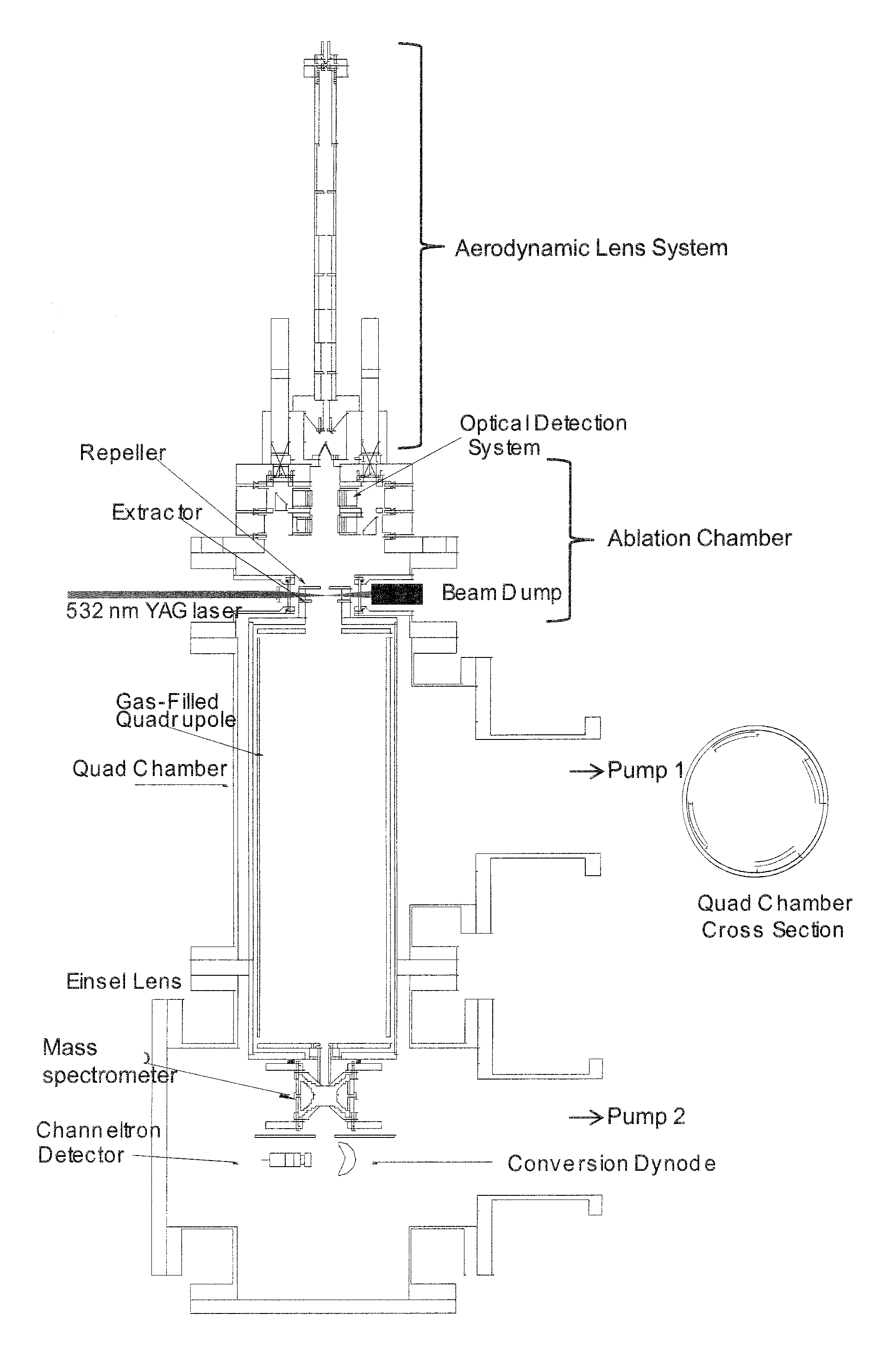
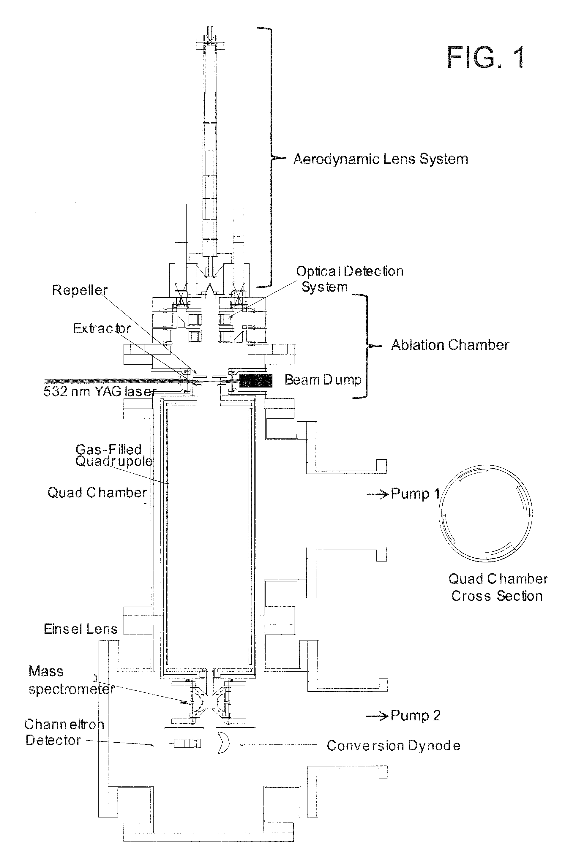
[0052]Referring to FIG. 1, a first exemplary instrumentation includes an aerosol particle supply system, an ablation chamber, a gas-filled conduit, and an ion trap mass spectrometer. The aerosol particle supply system and the ablation chamber are connected to each other through a first opening, which is an orifice at the outlet of the aerodynamic lens system. The ablation chamber and the gas-filled conduit are connected through a second opening. The gas-filled conduit and the ion trap are connected through a third opening. The ion trap mass spectrometer, and the gas-filled conduit are housed ...


PUM


Abstract

An aerosol particle analyzer includes a laser ablation chamber, a gas-filled conduit, and a mass spectrometer. The laser ablation chamber can be operated at a low pressure, which can be from 0.1 mTorr to 30 mTorr. The ablated ions are transferred into a gas-filled conduit. The gas-filled conduit reduces the electrical charge and the speed of ablated ions as they collide and mix with buffer gases in the gas-filled conduit. Preferably, the gas filled-conduit includes an electromagnetic multipole structure that collimates the nascent ions into a beam, which is guided into the mass spectrometer. Because the gas-filled conduit allows storage of vast quantities of the ions from the ablated particles, the ions from a single ablated particle can be analyzed multiple times and by a variety of techniques to supply statistically meaningful analysis of composition and isotope ratios.

Description

STATEMENT REGARDING FEDERALLY SPONSORED RESEARCH OR DEVELOPMENT [0001]This invention was made with United States government support under Prime Contract No. DE-AC05-000R22725 awarded by the U.S. Department of Energy. The United States government has certain rights in this invention.FIELD OF THE INVENTION [0002]The present invention relates to the field of analytical instrumentation and methods of operating the same.BACKGROUND OF THE INVENTION [0003]Analysis of aerosol particles by mass spectrometry provides useful information on the composition of the sample. For example, polluted air in cities may be sampled and analyzed to determine the source of pollutants in the city air. Lee et al., “Determination of the size distribution of polydisperse nanoparticles with single-particle mass spectrometry: The role of ion kinetic energy,” AEROSOL SCIENCE AND TECHNOLOGY 39 (2): 162-169 February (2005), provides an exemplary instrumentation that may be employed to analyze the composition of aero...

Claims


Application Information

Patent Timeline
Patent Type & Authority Applications(United States)
IPC IPC(8): H01J49/40B01D59/44
CPCH01J49/04H01J49/161H01J49/0481H01J49/0445
Inventor REILLY, PETER T.A.
Owner UT BATTELLE LLC
Why Eureka
Try Eureka