Air bag system for vehicle

Inactive Publication Date: 2010-10-07
HONDA MOTOR CO LTD
View PDF13 Cites 6 Cited by
  • Summary
  • Abstract
  • Description
  • Claims
  • Application Information

AI Technical Summary

Benefits of technology

[0019]According to the present invention, since a plurality of the guide portions are provided between which the vent hole is positioned, the blocking member can slide easily when the blocking member is released during the air bag extension from the restricted state into the free state, which may ensure the smooth unblocking operation of the blocking member for blocking up the vent hole, but at

Problems solved by technology

If such a vent hole is unblocked at the very initial state of expansion of the air bag, gas supplied from an inflator is leaked from the vent hole, which causes delay of the initial rise of the inner pressure of the air bag.
However, when the vent hole cover

Method used


Image

  • Air bag system for vehicle
  • Air bag system for vehicle
  • Air bag system for vehicle

Examples


Embodiment Construction

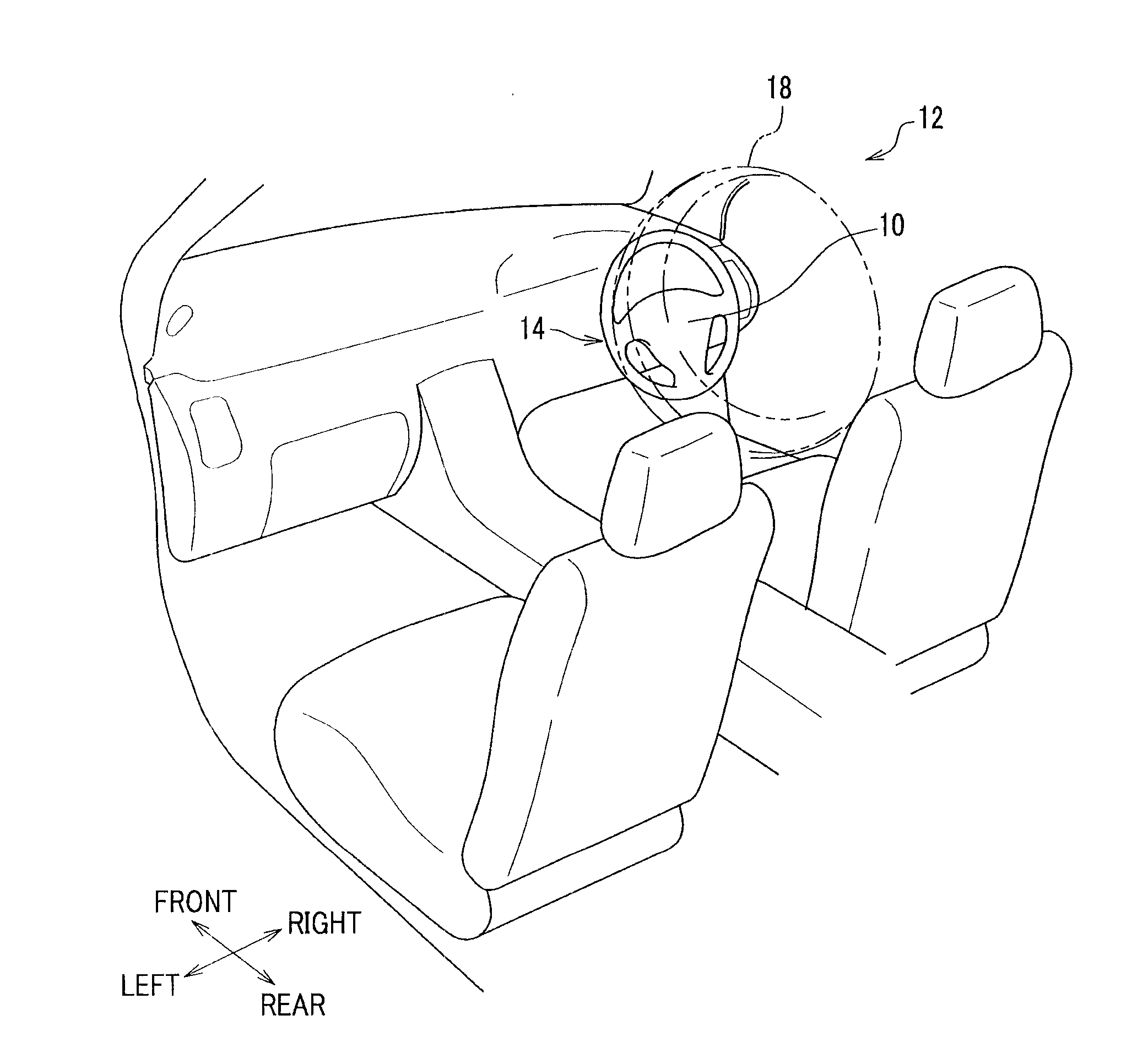
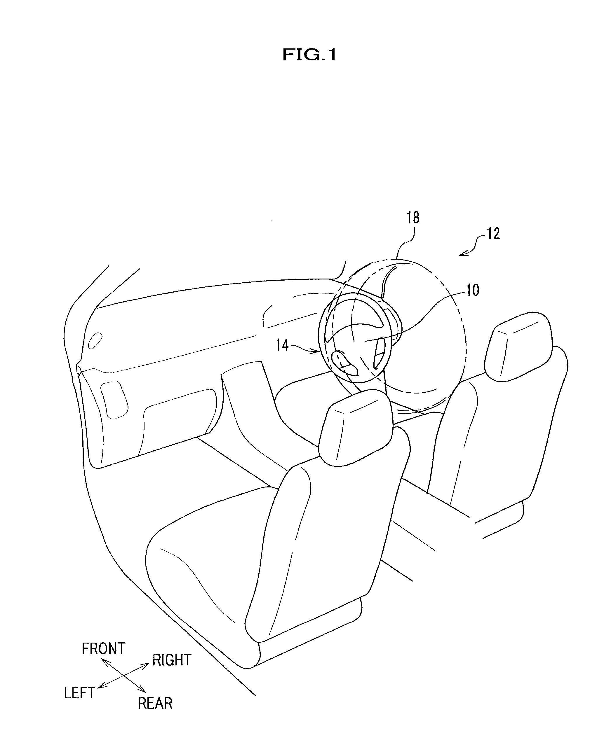
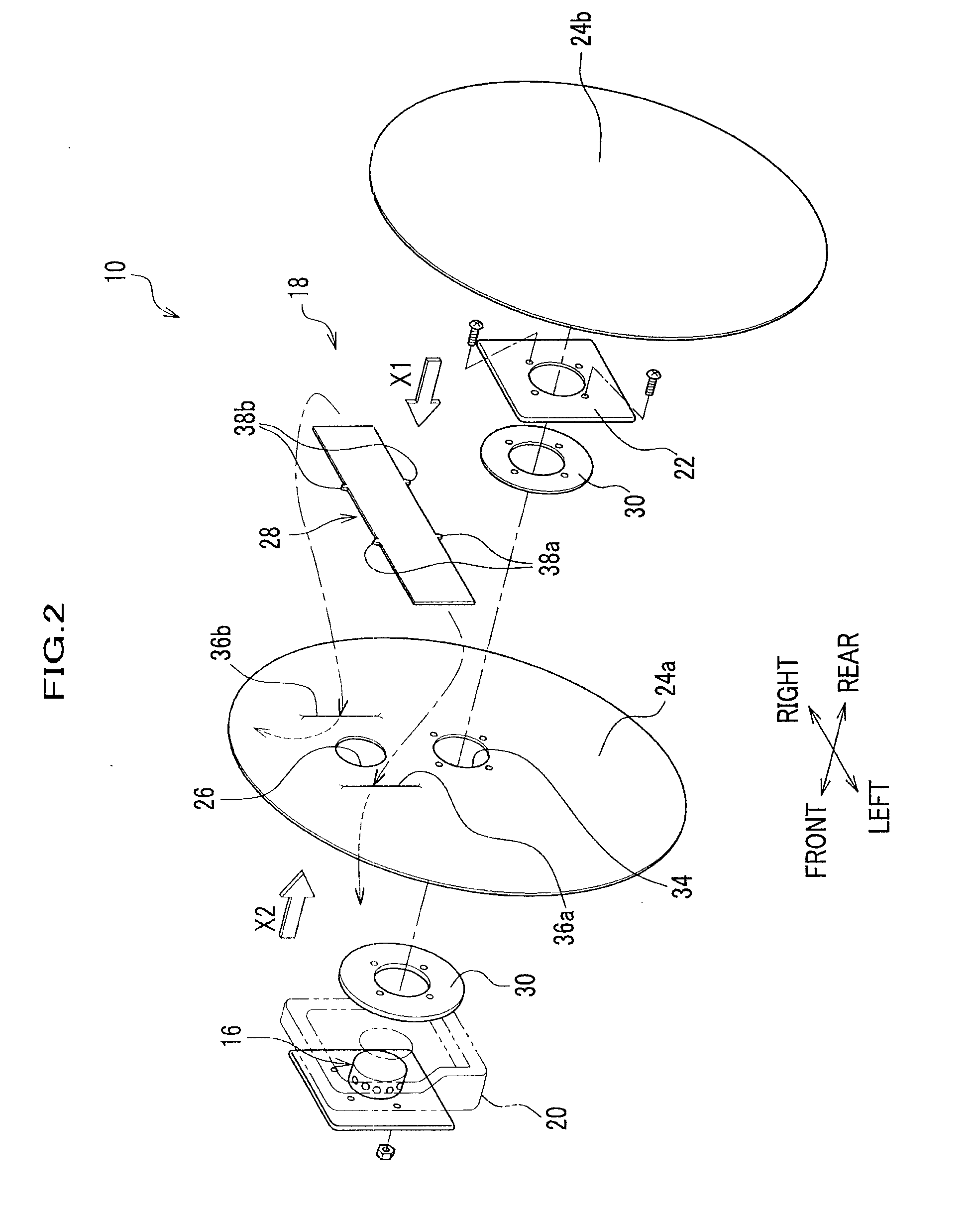
[0045]With reference to the drawings when necessary, descriptions are provided on the embodiment of the present invention hereinafter. FIG. 1 is a partially enlarged perspective view of a vehicle applied with an air bag system according to the embodiment of the present invention, and FIG. 2 is an exploded perspective view of the air bag system of FIG. 1.

[0046]The air bag system (air bag system for a vehicle) 10 according to the embodiment of the present invention is housed inside the steering wheel 14 installed in front of the driving seat. The air bag system 10 expands between the steering wheel 14 and a not shown driver to hold and protect the driver when collision energy is applied to the vehicle 12. The embodiment described hereinafter exemplifies the air bag system 10 housed inside the steering wheel 14, but the present invention is not limited to this, and may employ an air bag system of various types such as the air bag system housed inside an instrument panel at a driving se...


PUM


Abstract

An air bag system for a vehicle including an air bag in a folded state and installed in a vehicle. The air bag is inflated and expanded by gas from an inflator, which introduces gas into the air bag. A vent hole is formed in at least one base fabric piece of the air bag so as to establish a communication path between an inside and an outside of the air bag through which gas may be discharged from the inside toward the outside of the air bag. A blocking member is supported on the base fabric piece to block up the vent hole. A guide portion is provided to slidably support the blocking member and to restrict the position of the blocking member relative to the vent hole. A sliding resistance increasing portion is provided on at least either one of the guide portion and the blocking member, so as to increase a sliding resistance between the guide portion and the blocking member when the blocking member slides.

Description

CROSS-REFERENCE TO RELATED APPLICATION[0001]This application claims the foreign priority benefit under 35 U.S.C. §119 of Japanese Patent Application No. 2009-088851 filed on Apr. 1, 2009, the disclosure of which is incorporated herein by reference.BACKGROUND OF THE INVENTION[0002]1. Field of the Invention[0003]The present invention relates to an air bag system for a vehicle in which there is provided a vent hole in one of base fabric pieces that is a part of an air bag, so that gas flows from the vent hole toward the external during the expansion of the air bag.[0004]2. Description of the Related Art There has been known an air bag that inflates and expands by gas supply from an inflator at the time of a collision of a vehicle, thereby to protect an occupant. Such an air bag is provided with a vent hole for discharging gas at an excessive pressure to the external so as to prevent an excessive rise of gas pressure in the air bag.[0005]If such a vent hole is unblocked at the very init...

Claims


Application Information

Patent Timeline
IPC IPC(8): B60R21/26B60R21/16B60R21/239
CPCB60R21/2342B60R2021/2395B60R21/239
Inventor CHIDA, YUSUKENAGAI, MAKOTONOZAKI, HIROYUKI
Owner HONDA MOTOR CO LTD
Why Eureka
Try Eureka