Real-Time Reflection Point Density Mapping During Three-Dimensional (3D) Vertical Seismic Profile (VSP) surveys

a technology of vertical seismic profile and density mapping, which is applied in the field of generating borehole seismic surveys, can solve the problems of large and costly seismic datasets, increasing difficulty in recovering hydrocarbons from subsurface formations, and increasing complexity of seismic wave acquisition

Active Publication Date: 2010-10-07
SCHLUMBERGER TECH CORP
View PDF6 Cites 18 Cited by
  • Summary
  • Abstract
  • Description
  • Claims
  • Application Information

AI Technical Summary

Benefits of technology

[0028]In another refinement, a plurality of surface source points and the plurality of source firings are planned for each bin, and in part (5)(b), if the generated reflection point density is greater than the desired reflection point density, the plurality of surface source points and surface source firings planned for the bin is reduced.

Problems solved by technology

As the water depths increase and the wells that are drilled lengthen, recovery of hydrocarbons from subsurface formations becomes increasingly difficult and complex.
Although 3D VSPs are a valuable information tool for analyzing subsurface formations, acquisition of 3D VSP data by way of seismic waves that are generated by a surface source or seabed source is problematic.
First, the time required to acquire an effective 3D VSP can range from a few to several days, resulting in large and costly seismic datasets and substantial costs in terms of rig time.
Because of the time and expense involved in acquiring 3D VSPs, it is customary to acquire data outside of the important zones of interest as a safeguard against producing a 3D VSP with missing data, which results in additional costs and rig time.
Further, because of the time involved in acquiring 3D VSPs, surveys can be cut short for weather reasons or equipment malfunction, which can result in incomplete data sets.
Finally, data acquired from source firings at various locations in the survey may be poor, compromised and / or invalid due to various conditions beyond the control of the operator.
Because data problems may not be discovered until after the survey is complete and during subsequent data processing, it is sometimes necessary to go back to the wellsite and perform additional source firings in order to satisfactorily complete a VSP.
Further, each of the binning techniques illustrated in FIGS. 7-12 are post acquisition, and cannot readily be performed in real time.
However, this assumption is not always true and cannot be guaranteed during the survey.
If data from an adjacent bin is not available, the operator will not find out until after the survey is complete and the equipment has been withdrawn.
With marine 3D-VSP surveys acquired during rough sea conditions, control of the source location may be compromised, leading to uneven reflection point density coverage in the subsurface.
When using the binning techniques of FIGS. 7-12, this type of problem may result in oversized bins that seek to combine reflection points that are widely separated, thereby causing undesirable smearing of the data.

Method used


Image

  • Real-Time Reflection Point Density Mapping During Three-Dimensional (3D) Vertical Seismic Profile (VSP) surveys
  • Real-Time Reflection Point Density Mapping During Three-Dimensional (3D) Vertical Seismic Profile (VSP) surveys
  • Real-Time Reflection Point Density Mapping During Three-Dimensional (3D) Vertical Seismic Profile (VSP) surveys

Examples


Embodiment Construction

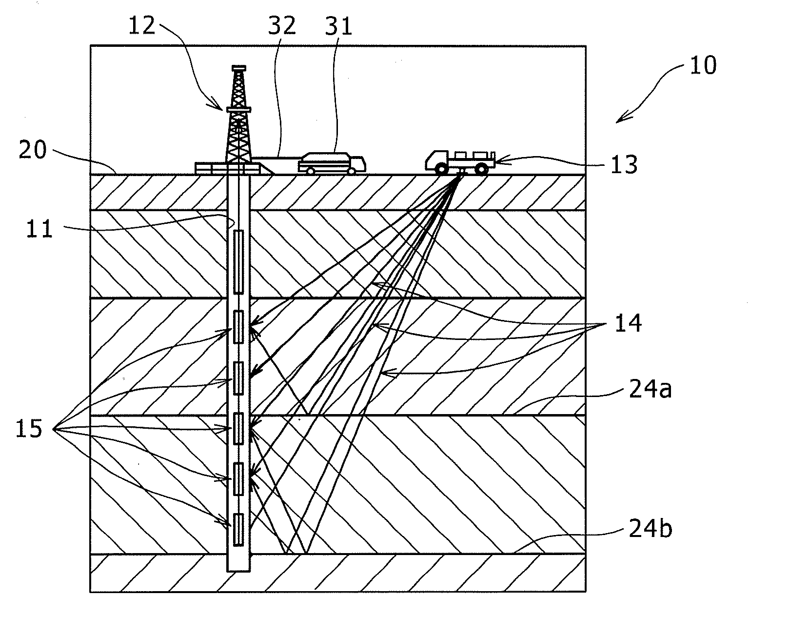
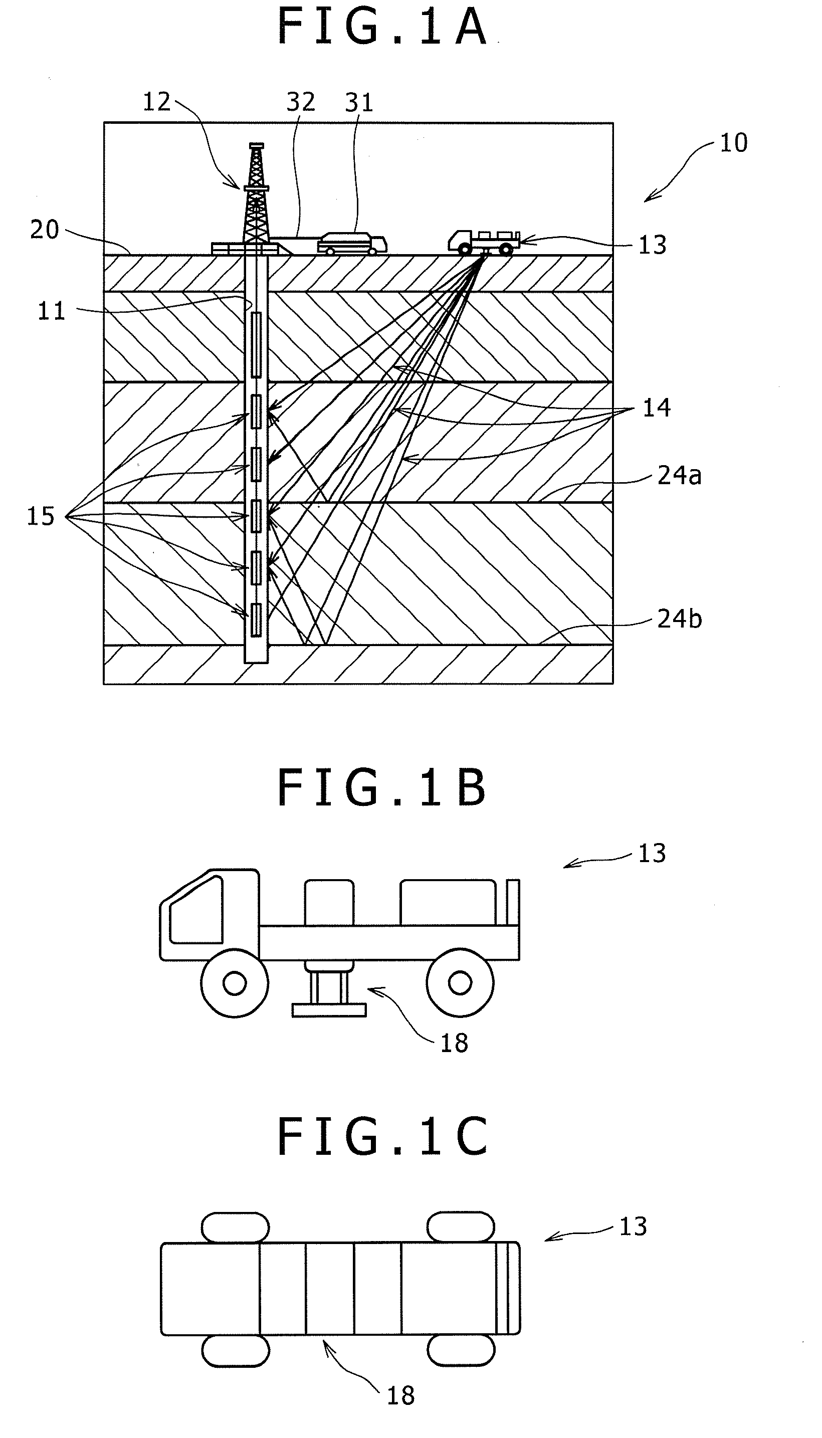
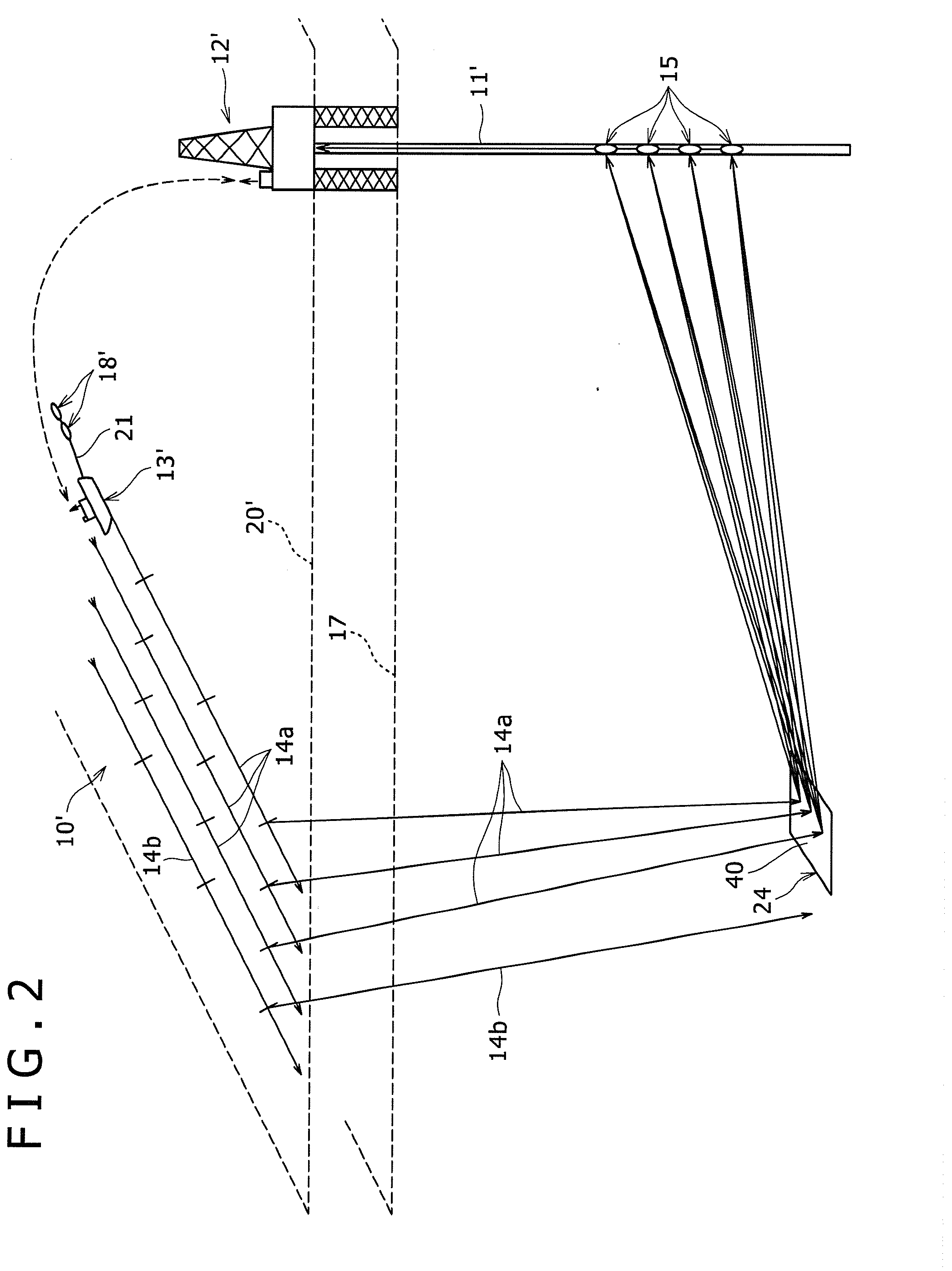
[0052]Referring to FIG. 1A, a general illustration is shown of a VSP survey 10 being conducted on a vertical well or borehole 11 that has been drilled using a land-based drill rig 12. A land-based movable seismic source vehicle 13 is also shown on the surface for generating seismic signals or source propagation paths shown generally at 14 at the surface 20 that are reflected off of one or more target reflectors 24a, 24b to be detected by an array of spaced-apart downhole directional receivers 15. The receivers 15 are in communication with a logging truck 31 via a wireline 32. The source vehicle 13 shown is intended to be illustrative of one or more seismic source vehicles that can be simultaneously placed at various azimuths around the borehole 11 and move from one location to another during the survey. FIGS. 1B and 1C illustrate a land-based source vehicle 13 with a vibrator or source element 18 while FIGS. 2, 3C, 6 and 14-16 illustrate a marine-based source vessel 13′ equipped wit...


PUM


Abstract

Methods and apparatuses are disclosed for generating three dimensional (3D) vertical seismic profiles (VSPs) in a more time efficient manner. The methods and apparatuses enable faster and more efficient VSP surveys than previous techniques. Real-time updating of the velocity model and real-time reflection point density calculations are carried out, which are used to determine the location of the next seismic source firing. In the event the data of a particular bin has an insufficient fold, common image points (CIPs) or reflection point density, additional source firings may be carried out prior to moving the source. Further, in the event the data of a particular bin is excessive in terms of the fold, CIPs or reflection point density before the planned source firings for the bin are completed, remaining source firings for that bin may be skipped to save time and improve the efficiency of the data collection.

Description

BACKGROUND[0001]1. Technical Field:[0002]Methods and apparatuses are disclosed for generating borehole seismic surveys. More specifically, this disclosure relates to the generation of three-dimensional (3D) vertical seismic profiles (VSP) in a time-efficient and cost-efficient manner. More particularly, instead of firing the seismic source at regular and predetermined intervals and / or predetermined locations, this disclosure discloses methods and apparatuses for real-time reflection point density mapping of the seismic data after one or more seismic source firings for evaluating the sufficiency of the data in one area or bin before subsequent source firings are carried out in another area or bin. The actual coordinates or locations of the source firings are more accurately accounted for using a GPS system. The disclosed methods enable 3D VSPs to be produced faster, more efficiently and with enhanced data quality.[0003]2. Description of the Related Art:[0004]Geophysical mapping techn...

Claims


Application Information

Patent Timeline
Patent Type & Authority Applications(United States)
IPC IPC(8): G01V1/28
CPCG01V1/42G01V1/303G01V1/003G01V2210/161
Inventor TULETT, JOHN RICHARDARMSTRONG, PHILIP NEVILLE
Owner SCHLUMBERGER TECH CORP
Why Eureka
Try Eureka