Frequency comb spectroscopy apparatus and method of frequency comb spectroscopy

Inactive Publication Date: 2015-12-10
CONSIGLIO NAT DELLE RICERCHE
View PDF1 Cites 9 Cited by
  • Summary
  • Abstract
  • Description
  • Claims
  • Application Information

AI Technical Summary

Benefits of technology

[0022]Applicants have realized that, using a generally “unwanted” characteristic of waveguides, i.e. their dispersion, greatly simplify the situation. The plurality of transmitted “peaks” is greatly reduced, due to the fact that only a very small interval of frequencies of the comb is coupled to the cavity. In particular, preferably, the number of transmitted frequencies can be reduced to a number which does not have to be resolved any more, i.e. the resulting transmitted number of different peaks lies within the desired resolution, therefore a single detector is enough.
[0023]In other

Problems solved by technology

Common cavity enhanced techniques, originally developed for gas spectroscopy, present well-known drawbacks when extended to liquid compounds.
For instance, introduc

Method used


Image

  • Frequency comb spectroscopy apparatus and method of frequency comb spectroscopy
  • Frequency comb spectroscopy apparatus and method of frequency comb spectroscopy
  • Frequency comb spectroscopy apparatus and method of frequency comb spectroscopy

Examples


example

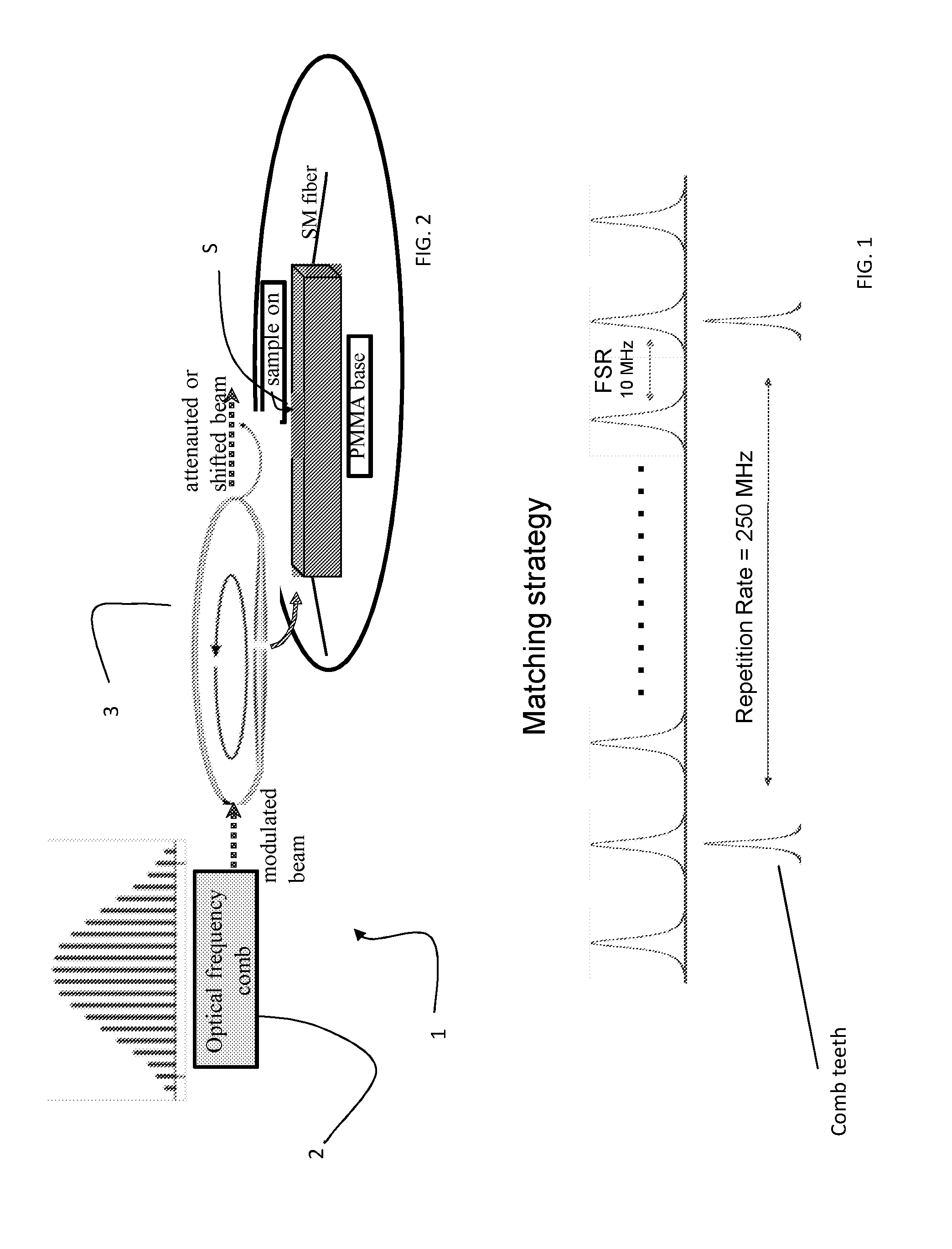
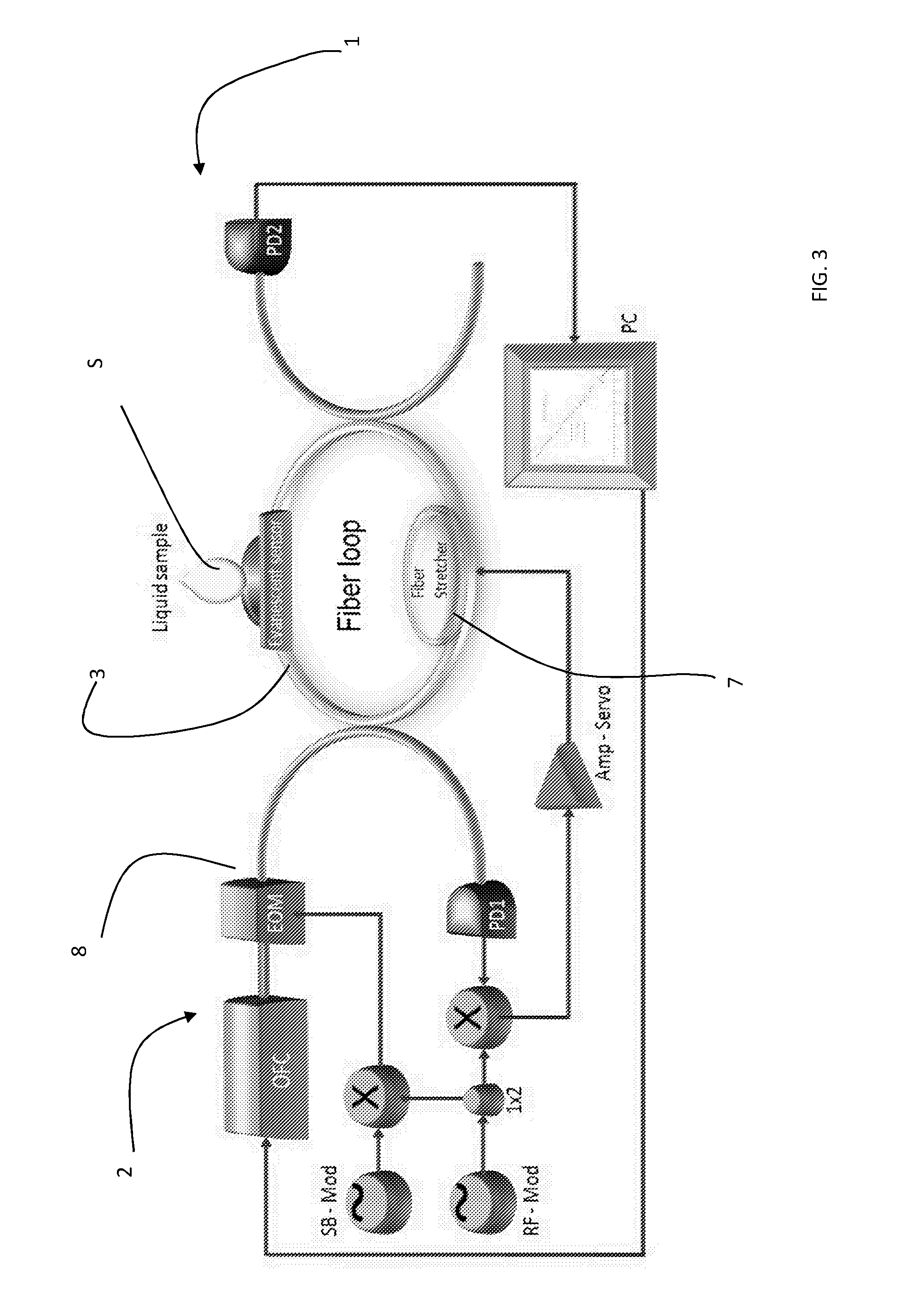
[0106]Reference is now made to FIG. 3 where a more detailed layout of the apparatus of the invention is sketched.

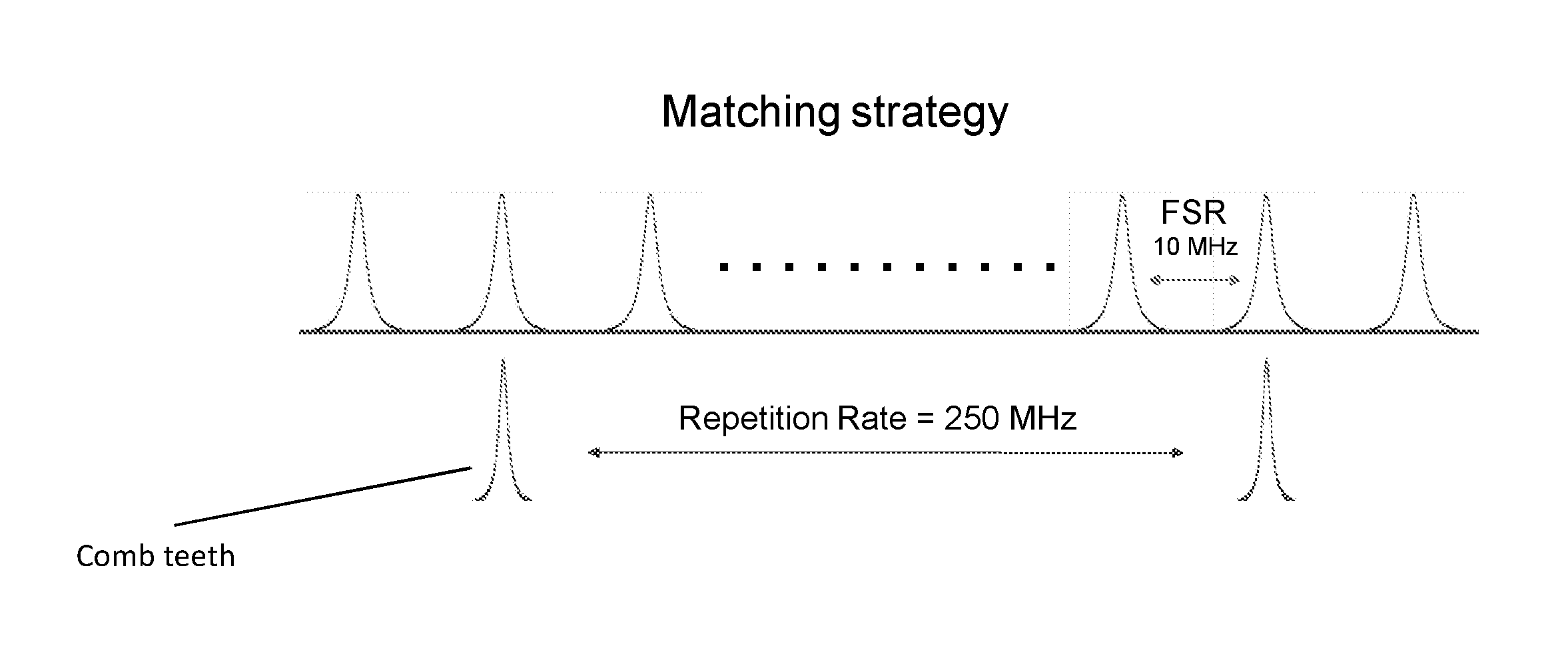
[0107]The sensing element, an evanescent-field access block (EAB) 3, consists of a single-mode optical fiber (SMF28 Corning) which is side-polished down to the core along a short length (˜1 mm): the resulting D-shaped fiber allows interaction of the cavity evanescent field with a chemical sample S nearby. The resulting D-shaped fiber allows interaction of the cavity evanescent field with the sample S over a 1 mm×0.125 mm area. Using absorption from known liquid species, the estimated effective EAB interaction length, rescaled by the actual penetration depth of the evanescent field, is of about 30 μm. The EAB is inserted into a 20.4-m fiber-loop cavity 3, whose length is finely controlled by a custom-built piezoelectric fiber-stretcher FS 7. The cavity 3 has a free spectral range (FSR) of 10 MHz and a finesse around 200, corresponding to a linewidth of 50 kHz.

[0108]The int...


PUM


Abstract

The present invention relates to a method and an apparatus to perform frequency comb spectroscopy. The method includes: —Arranging a waveguide optical cavity (3) having a plurality of cavity mode frequencies with a cavity mode frequency spacing (FSR), said waveguide optical cavity being dispersive so that the frequency spacing of the cavity modes is wavelength dependent; —Arranging a sample (S) with respect to the waveguide optical cavity (3) so that the sample is capable of absorbing light travelling into the waveguide optical cavity; —Coupling pulsed light coming from a light source (1) into the waveguide optical cavity (3), the source light including source comb frequencies (OCF) with a source frequency spacing (RR), the coupled light including an interval of frequencies centered on a main frequency of said comb frequencies due to cavity dispersion; —Locking the waveguide optical cavity to the frequency comb at said main optical frequency; —Detecting transmitted cavity frequencies; —Determining absorption by said sample (S) of said main optical frequency from the detected transmitted frequencies, —Changing the cavity mode frequency (FSR) spacing or the source frequency spacing (RR); —Coupling the pulse light to the waveguide optical cavity (3), the coupled light including an interval of frequencies centered on a second main frequency of said comb frequencies due to cavity dispersion; —Locking the waveguide optical cavity to the frequency comb at said second main optical frequency; —Detecting transmitted cavity frequencies; —Determining absorption by said sample of said second main optical frequency from the detected transmitted frequencies.

Description

TECHNICAL FIELD[0001]The present invention relates to an apparatus for performing frequency comb spectroscopy and a method to perform frequency comb spectroscopy. The apparatus and the method are designed in order to achieve sensitive and relatively simple measurements, in particular for liquid samples.BACKGROUND ART[0002]Laser spectroscopy is currently enabling a large number of experiment for scientific investigation. The development of new spectroscopic method and apparatuses is still in progress, to always obtain better monitoring and precise quantitative measurements of the physical world.[0003]Optical frequency combs (OFCs) led to impressive advances in the field of metrology and fundamental physics as detailed for example in J. Ye and S. T. Cundiff “Femtosecond optical frequency comb technology: principle, operation and application” (Springer, New York, 2005). In addition, OFCs have been proposed for a number of different applications, such as characterization of dispersion i...

Claims


Application Information

Patent Timeline
IPC IPC(8): G01N21/39
CPCG01N21/39G01N2201/06113G01N2201/08G01J3/0218G01J3/10G01J3/28G01J3/42G01N2021/391G01N2021/399G01J3/02G01J3/2803G01J2003/4332
Inventor GAGLIARDI, GIANLUCAAVINO, SAVERIOGIORGINI, ANTONIODE NATALE, PAOLO
Owner CONSIGLIO NAT DELLE RICERCHE
Why Eureka
Try Eureka