
Wireless communication adapter for a programmable logic controller and programmable logic controller system including the same

Inactive Publication Date: 2008-08-14
EATON CORP
View PDF14 Cites 36 Cited by
  • Summary
  • Abstract
  • Description
  • Claims
  • Application Information

AI Technical Summary

Benefits of technology

[0010]These needs and others are met by embodiments of the invention, which provide a wireless communication adapter for a programmable logic controller. The wireless communication adapter provides wireless connectivity to a number of input and output devices, such as, for example and without limitation, a number of wireless sensors or a number of wireless output devices. This reduces the plurality of wires providing inputs to and outputs from the programmable logic controller.

Problems solved by technology

Although relatively affordable, the major expense associated with intelligent relays or control relays is manual labor associated with installation of the system.
For example, there is a relatively substantial expense associated with wired electrical connections for the various I / O modules and a wired communication network.

Method used


Image

  • Wireless communication adapter for a programmable logic controller and programmable logic controller system including the same
  • Wireless communication adapter for a programmable logic controller and programmable logic controller system including the same
  • Wireless communication adapter for a programmable logic controller and programmable logic controller system including the same

Examples


example 1

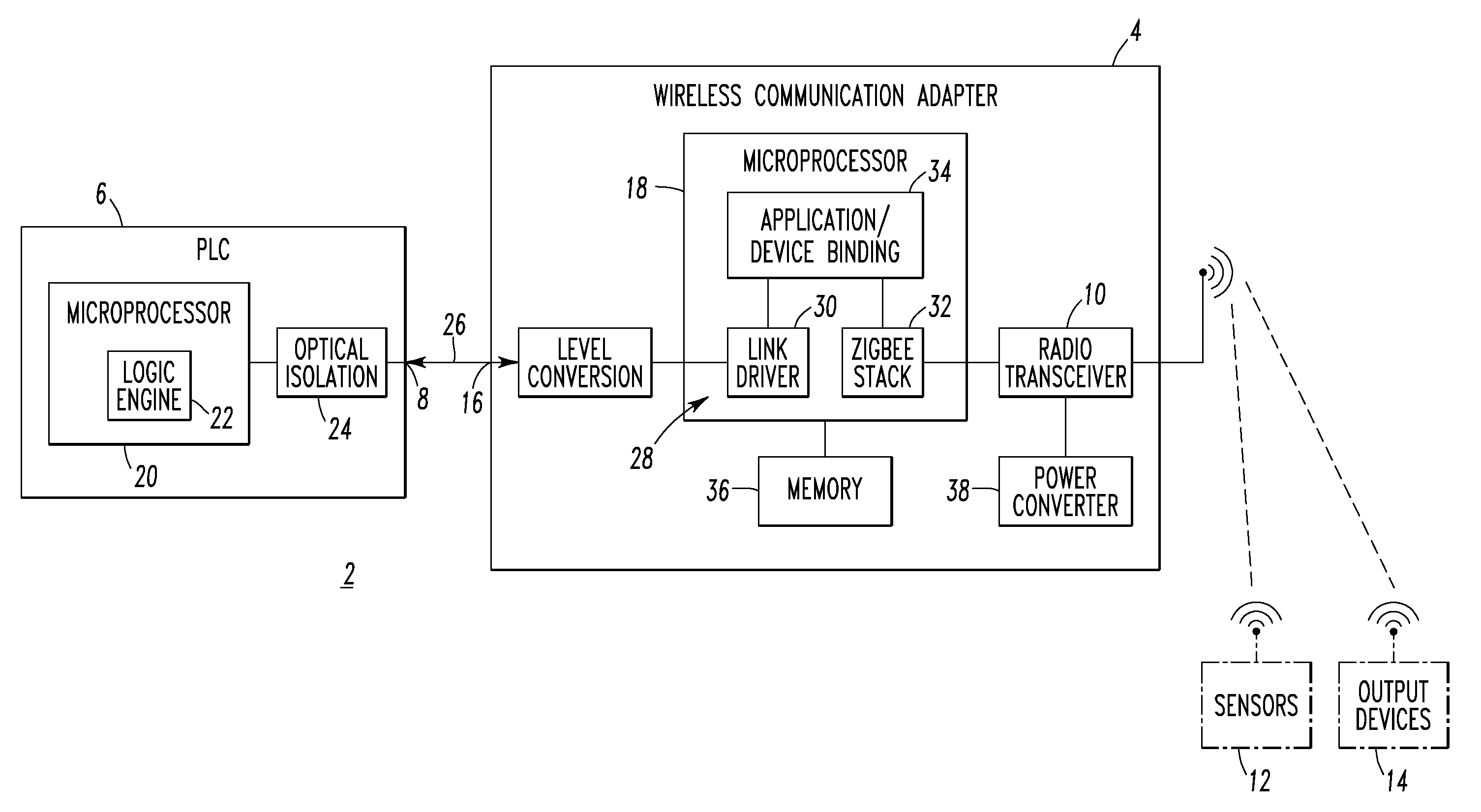
[0055]The example PLC 6 (e.g., without limitation, an EZ Intelligent Relay marketed by Eaton Electrical, Inc. of Milwaukee, Wis.) includes a microprocessor 20, a logic engine 22, which executes, for example, ladder diagrams, and an expansion port interface 24, which includes, for example and without limitation, optical isolation. The example EZ Intelligent Relay is a programmable switching and control device that is used as a replacement for relay and contactor control circuits. The EZ Intelligent Relay includes logic functions, timer, counter and time switch functions. It is also a control and input device in one that can perform many different tasks. Circuit diagrams are connected up using ladder diagrams, and each element is entered directly via a display (not shown). For example, functions supported by the PLC 6 include: connect make and break contacts in series and in parallel; connect output relays and markers; use outputs as relays, impulse relays or latching relays; use mult...

example 2

[0056]The example wireless communication adapter 4 is a wireless expansion module, which complements the PLC 6. The second wired communication port 16 and the PLC expansion port 8 interface a full-duplex, serial link 26, although any suitable wired interface (e.g., without limitation, a parallel bus) may be employed. The processor 18 includes suitable software components 28, namely a link driver 30 for the second wired communication port 16, a wireless protocol (e.g., without limitation, ZigBee™) stack 32 for the first wireless communication port 10, and an application / device binding routine 34 that communicates inputs from the remote wireless sensors 12 to the PLC expansion port 8 and communicates outputs from the PLC expansion port 8 to the remote wireless output devices 14. The wireless communication adapter 4 also includes a memory 36 and a power converter 38. Although a ZigBee™ stack 32 is disclosed, any suitable wireless communication protocol may be employed.

example 3

[0057]Preferably, the link driver 30 supports a suitable parallel communication protocol that supports a suitable count of inputs and outputs with respect to the PLC expansion port 8. As a non-limiting example, 16 discrete inputs and 8 discrete outputs are employed. Alternatively, any suitable count of inputs (e.g., digital; analog; logical) and any suitable count of outputs (e.g., digital; analog; logical) may be employed.


PUM


Abstract

A wireless communication adapter is for a programmable logic controller including a local wired communication port, such as an expansion port. The wireless communication adapter includes a first wireless communication port structured to wirelessly communicate with a plurality of remote wireless sensors and a plurality of remote wireless output devices. A second wired communication port is structured to communicate with the expansion port of the programmable logic controller. A processor cooperates with the first wireless communication port and the second wired communication port. The processor, the first wireless communication port and the second wired communication port are structured to communicate a plurality of inputs from the remote wireless sensors to the expansion port of the programmable logic controller and a plurality of outputs from the expansion port of the programmable logic controller to the remote wireless output devices.

Description

BACKGROUND OF THE INVENTION[0001]1. Field of the Invention[0002]This invention pertains generally to wireless communication and, more particularly, to wireless communication adapters for programmable logic controllers. The invention also pertains to programmable logic controller systems.[0003]2. Background Information[0004]A programmable logic controller (PLC) typically includes a plurality of analog and digital inputs and at least a number of digital outputs. PLCs are used in a wide variety of applications including, for example and without limitation, control of machinery on factory assembly lines, showroom and window store lighting systems, conveyor belt sequence control, temperature and ventilation control, and refrigerator control systems, among others. A PLC is preferably, but need not be, designed for one or more of extended temperature ranges, dirty or dusty conditions, immunity to electrical noise, and resistance to vibration and impact. PLC programs are normally stored in ...

Claims


Application Information

Patent Timeline
IPC IPC(8): H04B1/38
CPCH04W88/02G01D21/00
Inventor NAEVE, MARCODAS, SUJIT R.LUEBKE, CHARLES J.DEITS, GEORGE S.
Owner EATON CORP
Learn More