Heat-conducting system between two component parts and method for preparing a heat-conducting system

a heat-conducting system and component technology, applied in the direction of manufacturing tools, soldering apparatus, semiconductor/solid-state device details, etc., can solve the problems of critical, or rather not optimal, material reduction of heat-transmission resistance, and achieve the effect of simplifying the situation of the heat-conducting medium

Inactive Publication Date: 2013-03-14
ROBERT BOSCH GMBH
View PDF9 Cites 3 Cited by
  • Summary
  • Abstract
  • Description
  • Claims
  • Application Information

AI Technical Summary

Benefits of technology

[0007]In order to make possible the formation of the dendrites, on the one hand, and to simplify the situation of the heat-conducting medium between the component parts, on the other hand, without this leading to difficulties or disadvantages during the operation, as a result of a liquid or pasty heat-conducting medium, it is provided in one preferred specific embodiment that the heat-conducting medium is developed to be liquid or pasty in a processing state and solid in a final state.
[0008]It is especially preferred that the two component parts, at least at the contact surfaces to the heat-conducting medium, are made of electrically conductive material, particularly of metal. This creates the possibility of enabling the targeted developed of the dendrites between the two contact surfaces, by applying a voltage, and a current flow that is connected with it, in the heat-conducting medium.

Problems solved by technology

All these materials are, however, critical, or rather not optimal with respect to a combination of the following requirements: High thermal conductivity at high flexibility, high thermal conductivity without the use of electrically conductive materials, high reduction in heat transfer resistance by a good thermal connection to the respective joining partner.

Method used


Image

  • Heat-conducting system between two component parts and method for preparing a heat-conducting system
  • Heat-conducting system between two component parts and method for preparing a heat-conducting system

Examples


Embodiment Construction

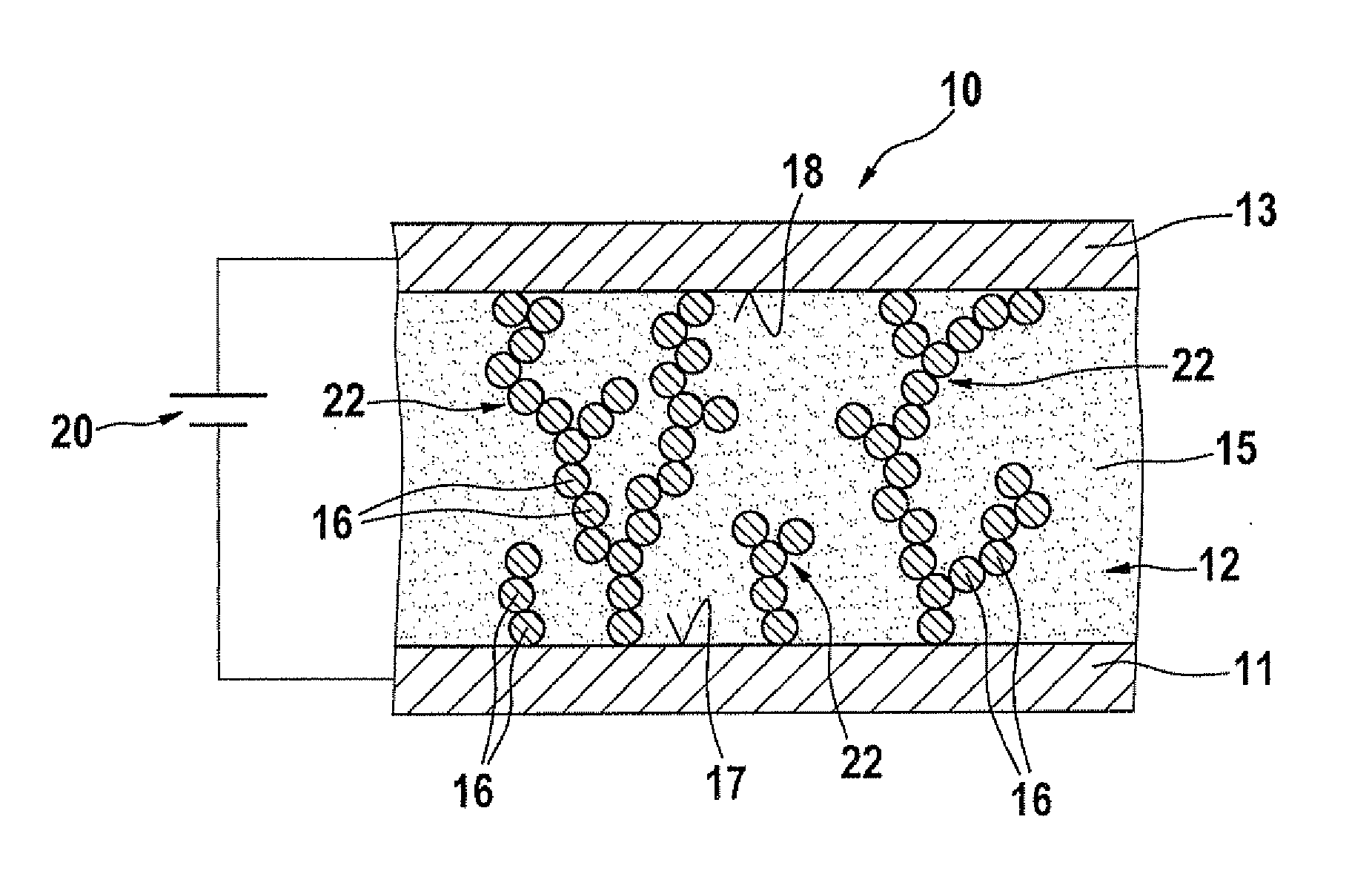
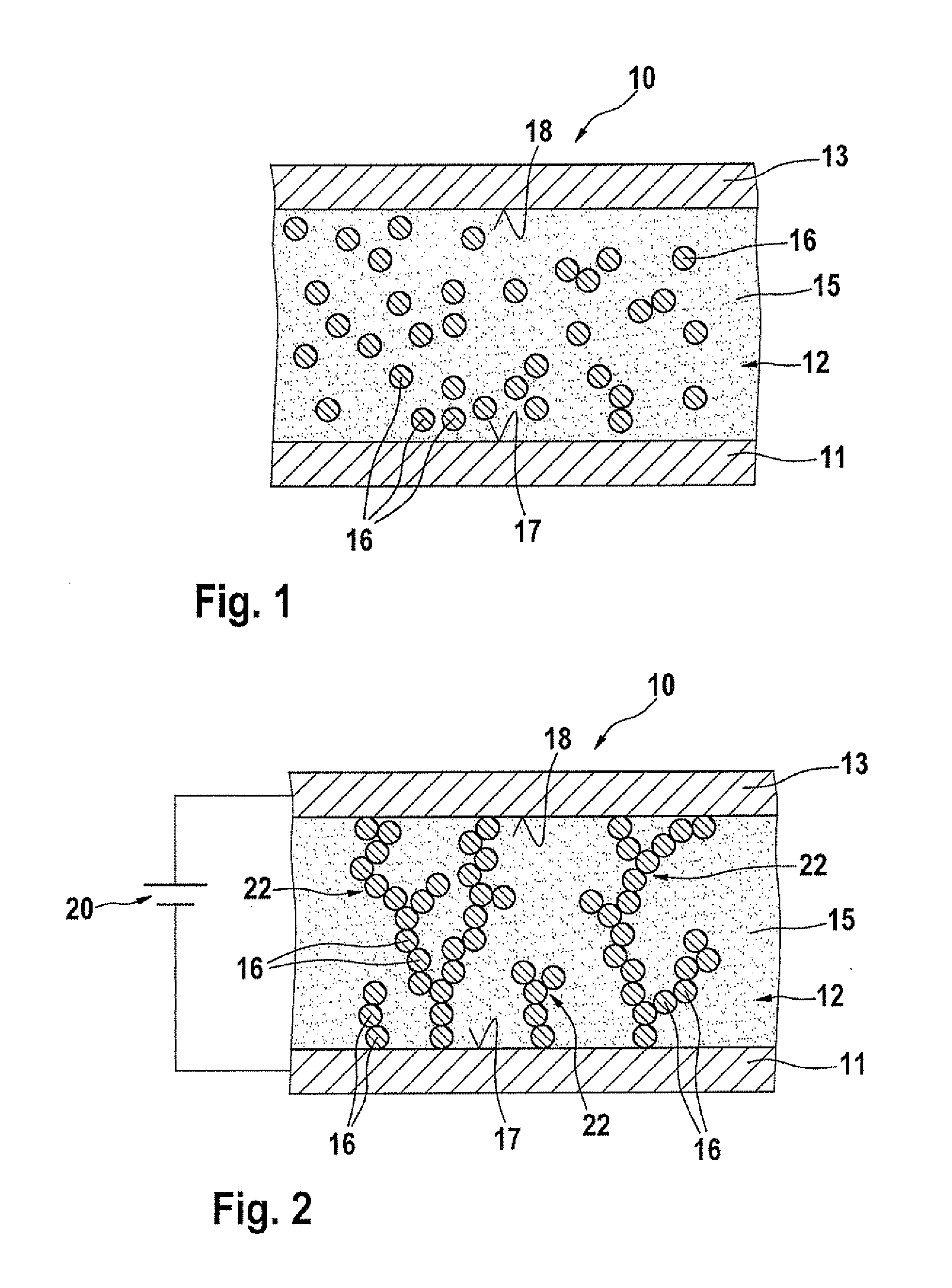
[0016]FIG. 1 shows a system10, made up of a first component part 11, an heat-conducting medium 12 and a second component part 13. In this instance, first component part 11 may be, for example, but not restrictively, an heat-generating electrical or electronic component part, such as a power transistor, an IC or the like. Second component part 13, is in turn, for example, but not restrictively developed as a heat-dissipating component part, such as a cooling element, which is to give off the heat generated by first component part 11 to the surroundings.

[0017]The heat-conducting medium is made up of a carrier material 15, especially in the form of a polymer matrix, in which, in the initial state, as shown in FIG. 1, metal salts in the form of metal ions 16 are mixed in, which are situated more or less uniformly in carrier material 15. As metal ions 16, copper ions and / or iron ions and / or aluminum ions and / or silver ions are used. There is at first no contact, as a rule, between the in...


PUM

PropertyMeasurementUnit
heat-conductingaaaaaaaaaa
electrically conductingaaaaaaaaaa
metallicaaaaaaaaaa

Abstract

A heat-conducting system has a heat-generating first component part and a second component part for dissipating the heat of the first component part, the two component parts being situated in operative connection to each other using a heat-conducting medium. The heat-conducting medium includes metal constituents, particularly metal ions, which are situated in a carrier material, especially in a polymer matrix; and the heat-conducting medium at an end state has dendrites made of the metal constituents, which are connected to the contact surfaces of the two component parts in a heat-conducting manner.

Description

BACKGROUND OF THE INVENTION[0001]1. Field of the Invention[0002]The present invention relates to a heat-conducting system between two component parts, and a method for preparing a heat-conducting system between two component.[0003]2. Description of the Related Art[0004]Such a system, or method for preparing such a system, is known from the related art. In this context, for example, a heat-generating first component part is connected to a heat-dissipating, second component part, such as a cooling element, via a medium. The medium, in this instance, is made up either of a paste, for example, which does not harden, as a so-called “gap filler, of which portions harden, or of a heat-conducting film or a heat-conducting adhesive substance, the two last-named media hardening fully, as a rule. The materials named are mostly filled up very highly by inorganic materials, such as silver, aluminum oxides, boron nitrides or carbon. In addition, there exist so-called “phase change materials” (PCM...

Claims


Application Information

Patent Timeline
Patent Type & Authority Applications(United States)
IPC IPC(8): H05K7/20H05K13/00
CPCC09K5/14H01L23/3737H01L23/42H01L24/29H01L24/83H01L2224/2929H01L2924/0002H01L2224/293H01L2224/32245H01L2924/00H01L2224/83851C09K5/08
Inventor SCHUETT, KLAUS-VOLKERWAHL, RUBEN
Owner ROBERT BOSCH GMBH
Why Eureka
Try Eureka