Apparatus With a Directly Driven Rotating Body and Aerostatic Bearings

a technology of rotating body and bearing, applied in the direction of bearings, shafts, rotary machine parts, etc., can solve the problems of local deformation of the rotating body in the axial direction, and achieve the effect of reducing the effects of a “magnetic imbalance”

Active Publication Date: 2010-10-07
AEROLAS GMBH AEROSTATISCHE LAGER LASERTECHN
View PDF19 Cites 14 Cited by
  • Summary
  • Abstract
  • Description
  • Claims
  • Application Information

AI Technical Summary

Benefits of technology

[0008]It is therefore an object of the present invention to provide a device as generally described above that significantly reduces the effects of a

Problems solved by technology

Instead, they only result in a local deformati

Method used


Image

  • Apparatus With a Directly Driven Rotating Body and Aerostatic Bearings
  • Apparatus With a Directly Driven Rotating Body and Aerostatic Bearings
  • Apparatus With a Directly Driven Rotating Body and Aerostatic Bearings

Examples


Embodiment Construction

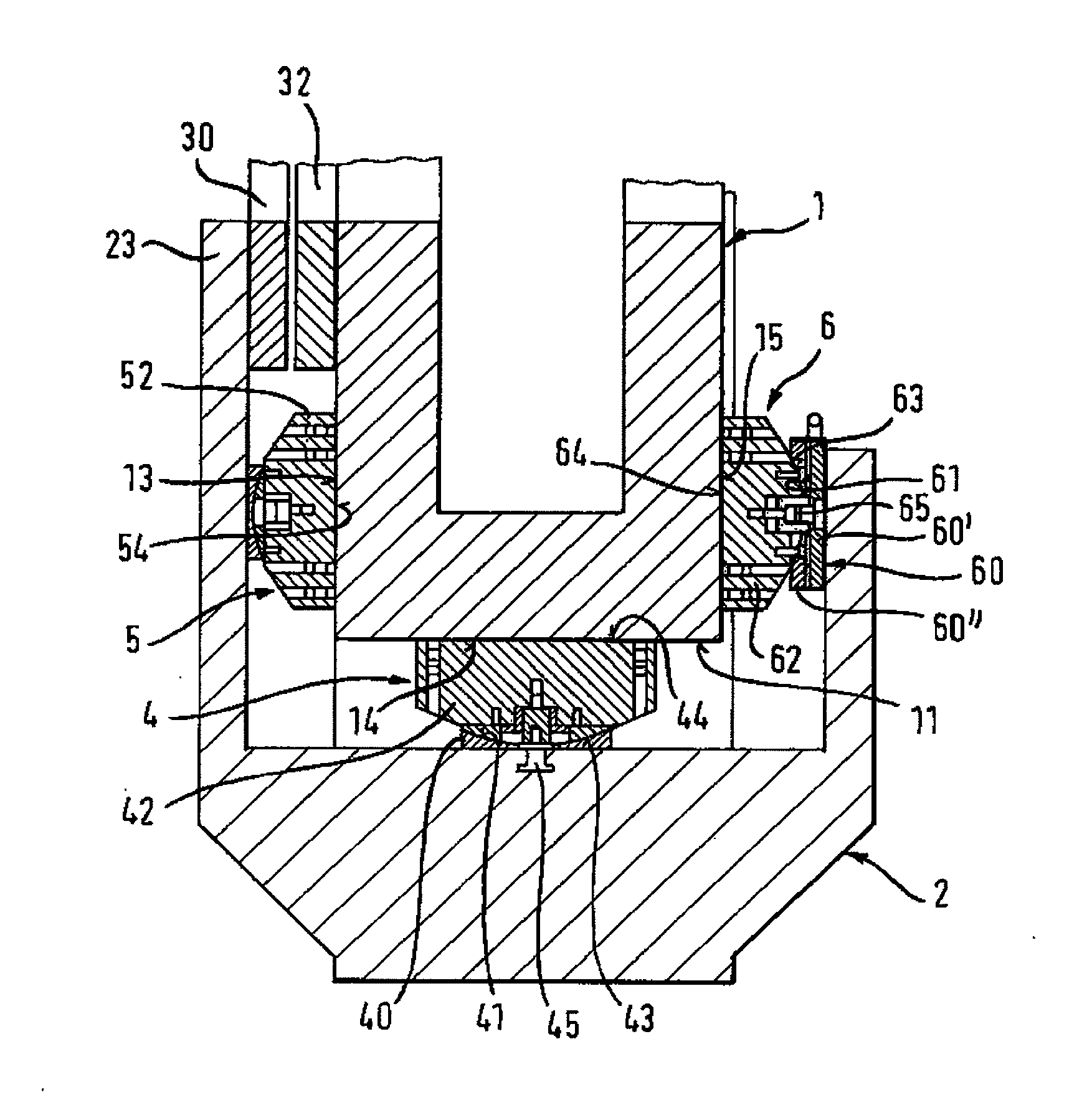
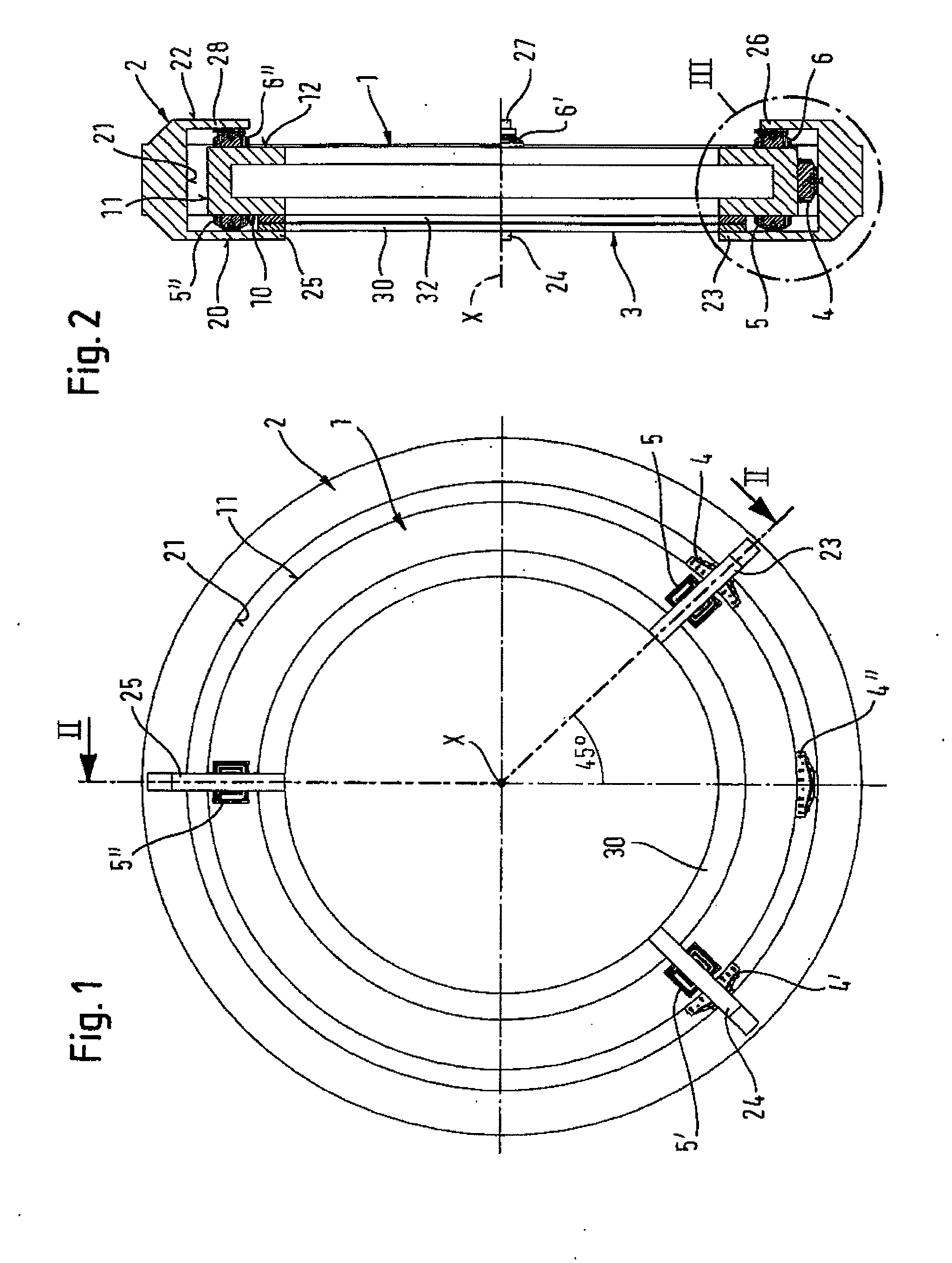
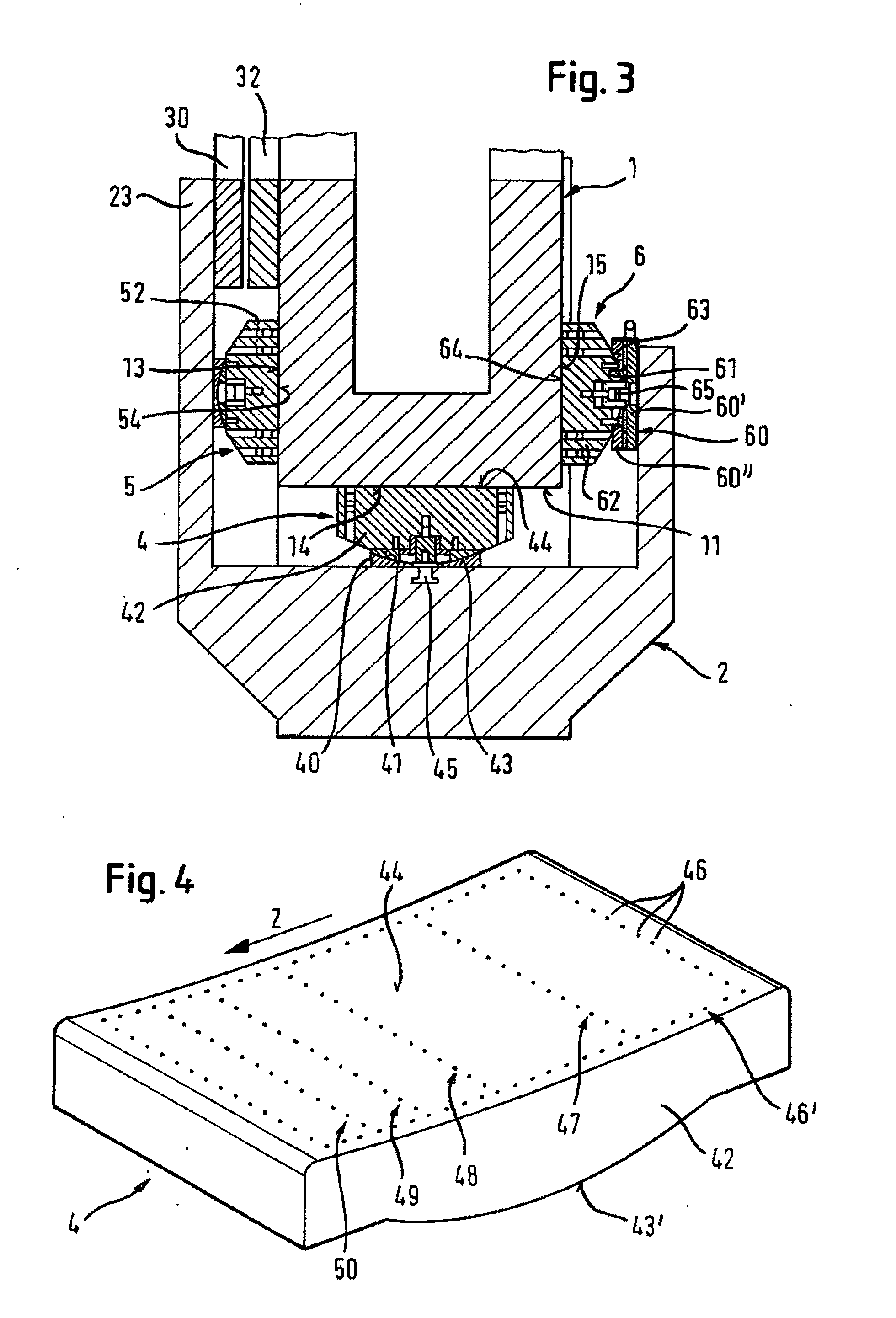
[0029]FIGS. 1 and 2 show an inventive device, as implemented, for example, in a CT scanner. An annular rotating body 1 is arranged in the interior of a stationary body 2. The outer stationary body 2 can be the stationary gantry of a CT scanner, and the inner rotating body 1 can be the rotating gantry of a CT scanner, on which the imaging apparatus (not illustrated) of the CT scanner is mounted.

[0030]A first face side 20 of the stationary body 2 has three radial lands 23, 24, 25, which point radially inwards and which carry on their respectively radially inner ends an annular electric coil arrangement 30 of the axial electric direct drive 3.

[0031]On a first face side 10 of the rotating body 1 located opposite the coil arrangement 30 in the axial direction is an annular magnet arrangement 32 of the electric direct drive 3. Both the annular magnet arrangement 32 and the electric coil arrangement 30, which is also ring-shaped, are arranged coaxially to the axis of rotation (X) of the ro...


PUM


Abstract

A device having a directly driven rotating body (1), its circumference (11) being radially seated on radial bearings (4, 4′) in relation to the stationary body (2), and its at least one first face side (10) being axially seated in relation to the stationary body (2), wherein aerostatic bearings (5, 5′, 5″) are provided for the axial support mounting, characterized in that the first face side (10) has an annular magnet arrangement (32), which is configured coaxially to the axis of rotation (X) of the rotating body (1), and that the stationary body (2) has at least one electric coil arrangement (30), which is located opposite the annular magnet arrangement (32) in the axial direction and which forms together with the annular magnet arrangement (32) the components of an electrical direct drive (3) for the rotating body (1).

Description

RELATED APPLICATIONS[0001]This application claims the priorities of German Patent Application No. 10 2006 037 543.2 filed Aug. 10, 2006 and of PCT Application No. PCT / EP / 2007 / 007098 filed Aug. 10, 2007, the disclosures of which are incorporated herein by reference.BACKGROUND OF THE INVENTION[0002]The invention relates to an apparatus having a directly driven rotating body in accordance with the preamble of claim 1 and to an aerostatic bearing in accordance with the preamble of claim 12.[0003]Such devices are known from WO 02 / 089671 A2, which discloses an aerostatic rotor bearing for the rotating annular gantry of a computed tomography (CT) scanner. The construction of such CT scanners is generally known, for example, from that document. The disclosure of WO 02 / 089671 A2 is explicitly referred to herein with respect to the construction of a CT scanner, and its disclosure is incorporated herein by reference.[0004]An imaging apparatus is typically mounted on the annular gantry of a CT ...

Claims


Application Information

Patent Timeline
IPC IPC(8): F16C32/06
CPCA61B6/035F16C32/0666F16C32/0618A61B6/56F16C2300/14F16C2316/10
Inventor MUTH, MICHAEL
Owner AEROLAS GMBH AEROSTATISCHE LAGER LASERTECHN
Why Eureka
Try Eureka