User equipment terminal and signal power measurement method

Inactive Publication Date: 2010-10-07
NTT DOCOMO INC
View PDF9 Cites 17 Cited by
  • Summary
  • Abstract
  • Description
  • Claims
  • Application Information

AI Technical Summary

Benefits of technology

[0024]According to an embodiment of the present invention, it is possible to achieve high quality in hando

Problems solved by technology

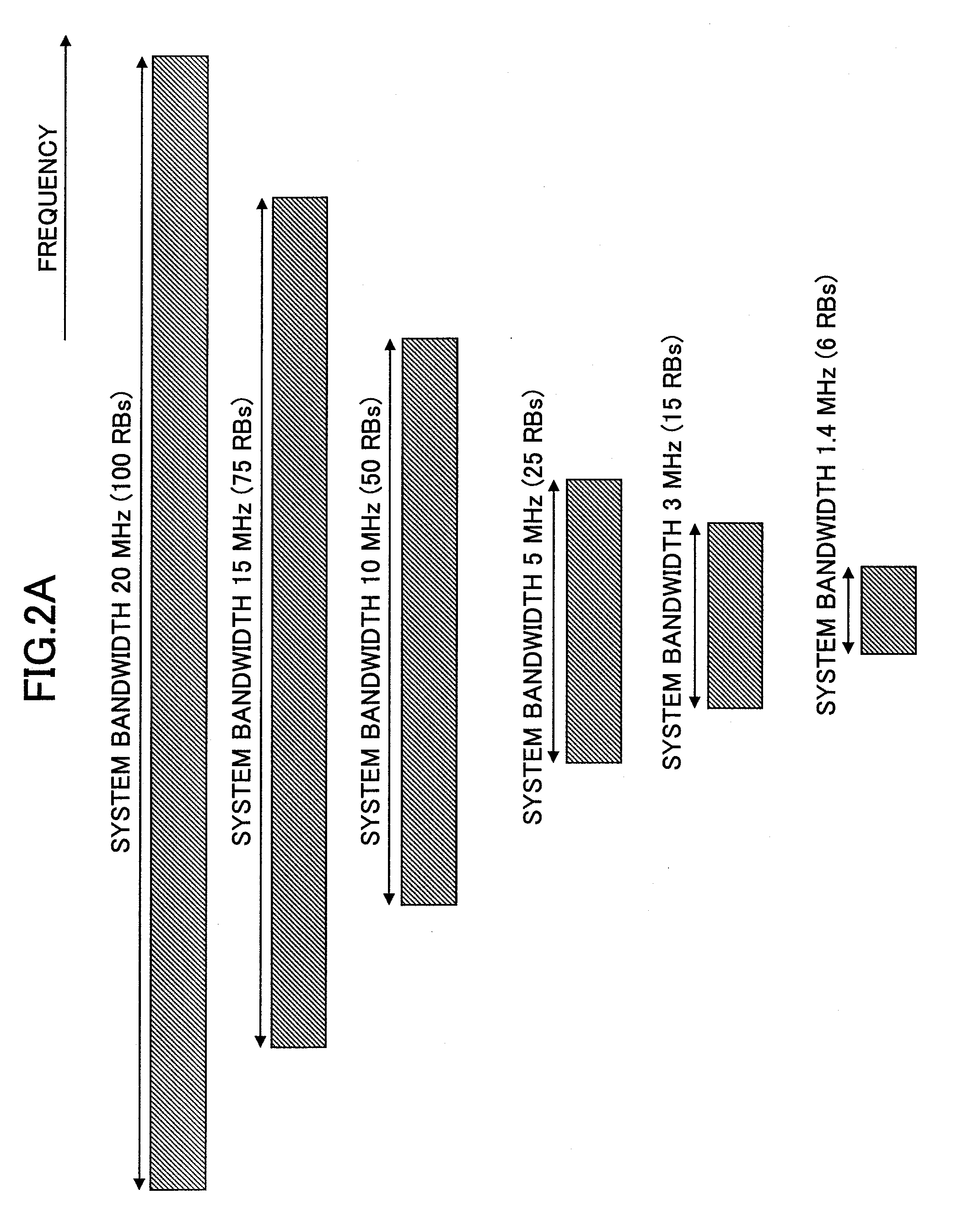
Measurement of RSRP within such a narrow bandwidth needs a longer measurement

Method used


Image

  • User equipment terminal and signal power measurement method
  • User equipment terminal and signal power measurement method
  • User equipment terminal and signal power measurement method

Examples


Embodiment Construction

Description of Notations

[0032]10 user equipment terminal[0033]101 receiving unit[0034]102 movement speed estimating unit[0035]103 measurement bandwidth determining unit[0036]104 GPS unit[0037]105 handover count retrieving unit[0038]106 FFT processing unit

BEST MODE OF CARRYING OUT THE INVENTION

[0039]With reference to the accompanying drawings, embodiments of the present invention are described below.

[0040]FIG. 4 shows a relationship between an estimated movement speed and a measurement bandwidth of signal power in accordance with an embodiment of the present invention. In this embodiment, a user equipment terminal estimates the movement speed of the user equipment terminal, determines a measurement bandwidth based on the estimated movement speed, and measures signal power (RSRP) within the determined measurement bandwidth.

[0041]For example, as shown in FIG. 4, when the estimated movement speed is fast (fast movement), the measurement bandwidth is determined to be equal to fifty resou...


PUM


Abstract

A user equipment terminal for measuring signal power in a neighbor cell includes a movement speed estimating unit configured to estimate a movement speed of the user equipment terminal or a fading frequency of a propagation; a measurement bandwidth determining unit configured to determine a measurement bandwidth according to the movement speed or the fading frequency of the propagation; and a measurement unit configured to measure signal power in the neighbor cell within the determined measurement bandwidth.

Description

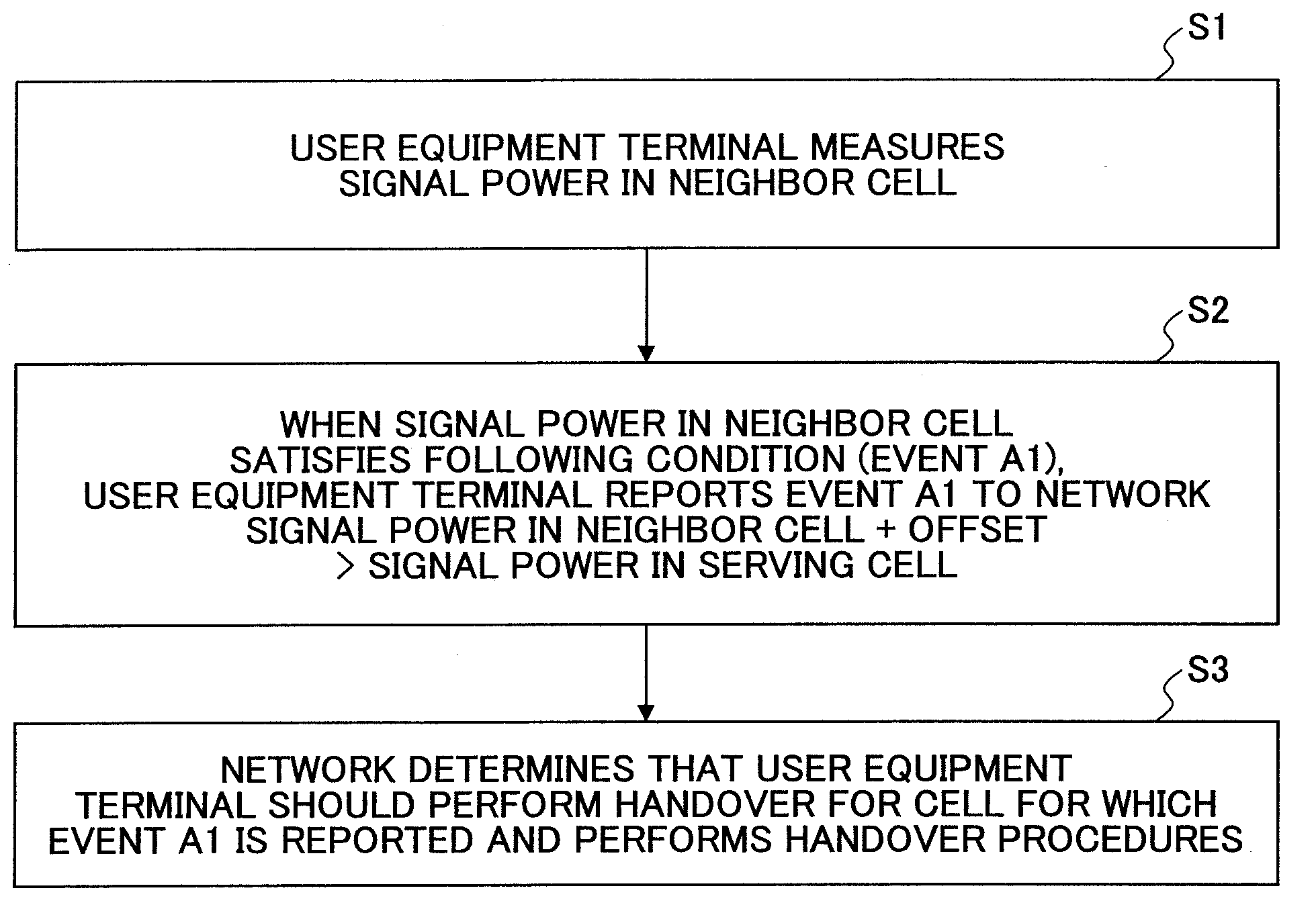
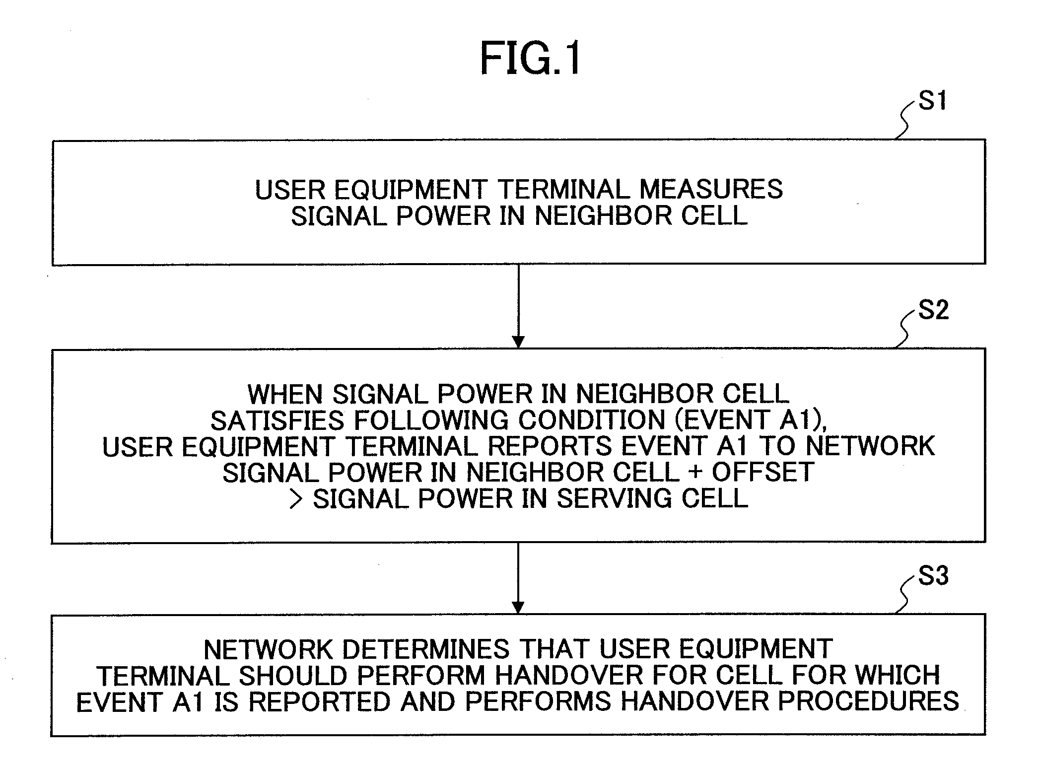
TECHNICAL FIELD[0001]The present invention relates to a user equipment terminal and a signal power measurement method.BACKGROUND ART[0002]In a mobile communication system including plural cells, when a user equipment terminal (UE: user equipment) moves from one cell to another, the user equipment terminal switches to the other cell to continue communications. The switching to the other cell is referred to as handover. Typically, when the user equipment terminal moves to a neighbor cell and signal strength in the neighbor cell is higher than signal strength in the serving cell (cell in which the user equipment terminal originally performs communications), the user equipment terminal performs handover to the neighbor cell.[0003]Specifically, the user equipment terminal performs handover according to the procedure shown in FIG. 1.[0004]First, the user equipment terminal measures signal power in the neighbor cell (S1). Then, the user equipment terminal determines whether the signal powe...

Claims


Application Information

Patent Timeline
IPC IPC(8): H04W24/00
CPCH04W64/006H04W36/0094H04B17/318H04B17/382H04W36/30H04W36/0061H04W36/32H04W24/04H04W48/04
Inventor ISHII, HIROYUKI
Owner NTT DOCOMO INC
Why Eureka
Try Eureka