Sonic screw

Inactive Publication Date: 2010-10-07
STRYKER EURO OPERATIONS HLDG LLC
View PDF27 Cites 34 Cited by
  • Summary
  • Abstract
  • Description
  • Claims
  • Application Information

AI Technical Summary

Benefits of technology

[0007]One aspect of the invention may be to provide a screw and a method by means of which a r

Problems solved by technology

This system has the drawback that the manual pressure applied to the fixation cement varies, not only basically from application to application, but also duri

Method used


Image

  • Sonic screw
  • Sonic screw
  • Sonic screw

Examples


Embodiment Construction

[0039]FIGS. 1 to 6 are a schematic illustration showing different steps in the use of a set of devices for installation of a screw according to the invention.

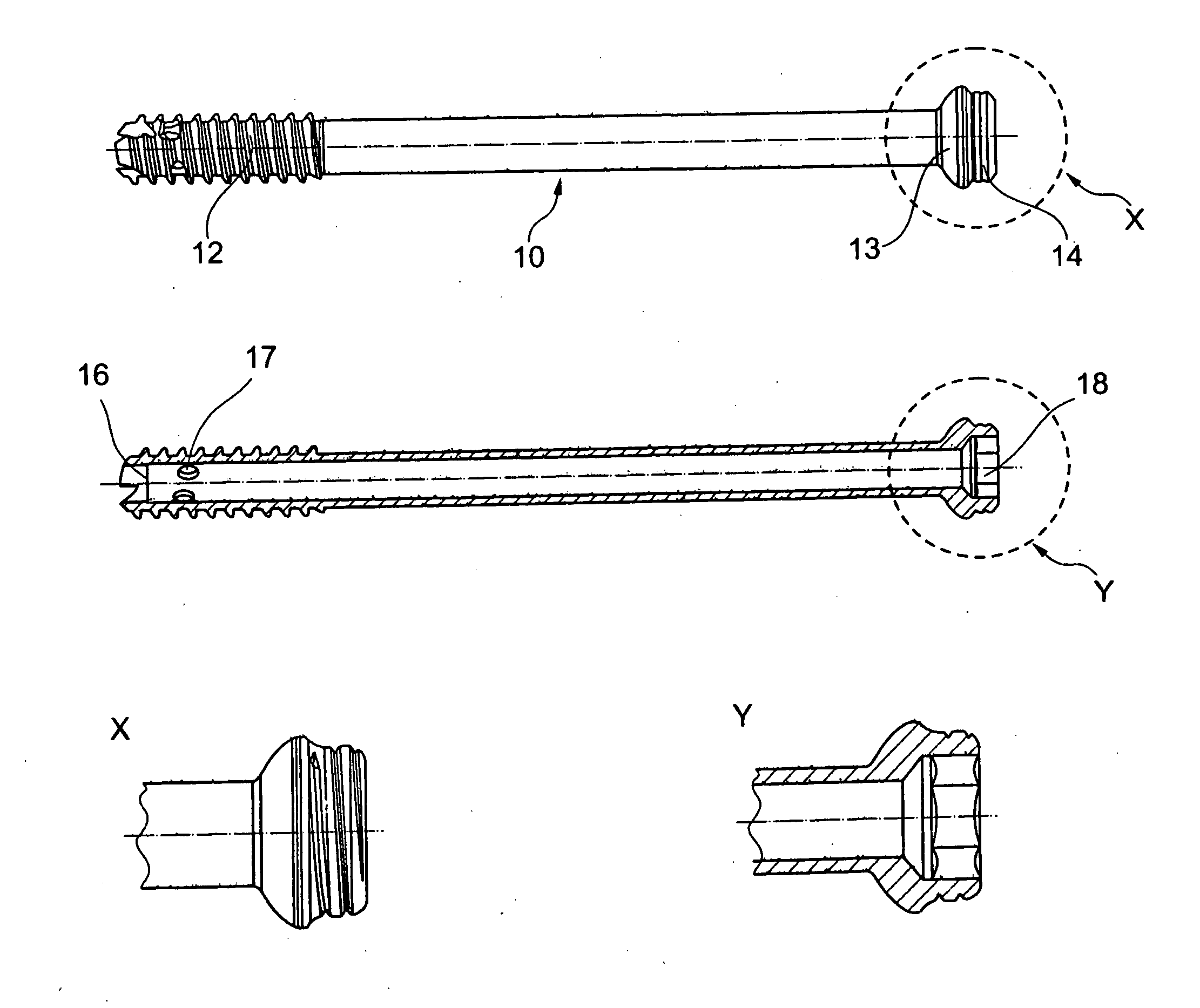
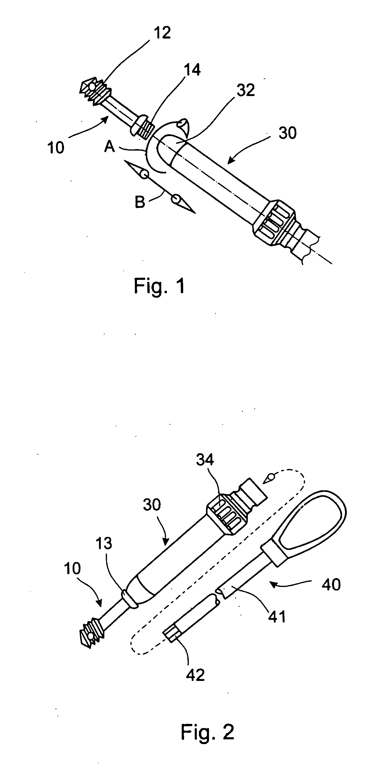
[0040]FIG. 1 shows a screw 10 including a first outer thread 12 and a second outer thread 14. A tissue protection sleeve 30 is shown with a small distance behind the second outer thread 14 of screw 10. Furthermore, there is indicated by arrow A that the tissue protection sleeve may be screwed onto the second outer thread 14. Even though the arrow A indicates a right hand thread, a left hand thread may also suitable.

[0041]Consequently, a distal end 32 of tissue protection sleeve 30 is provided with an inner thread corresponding to outer thread 14 of screw 10. The arrow B indicates that a force transmission from the tissue protection sleeve to the screw is possible in axial direction.

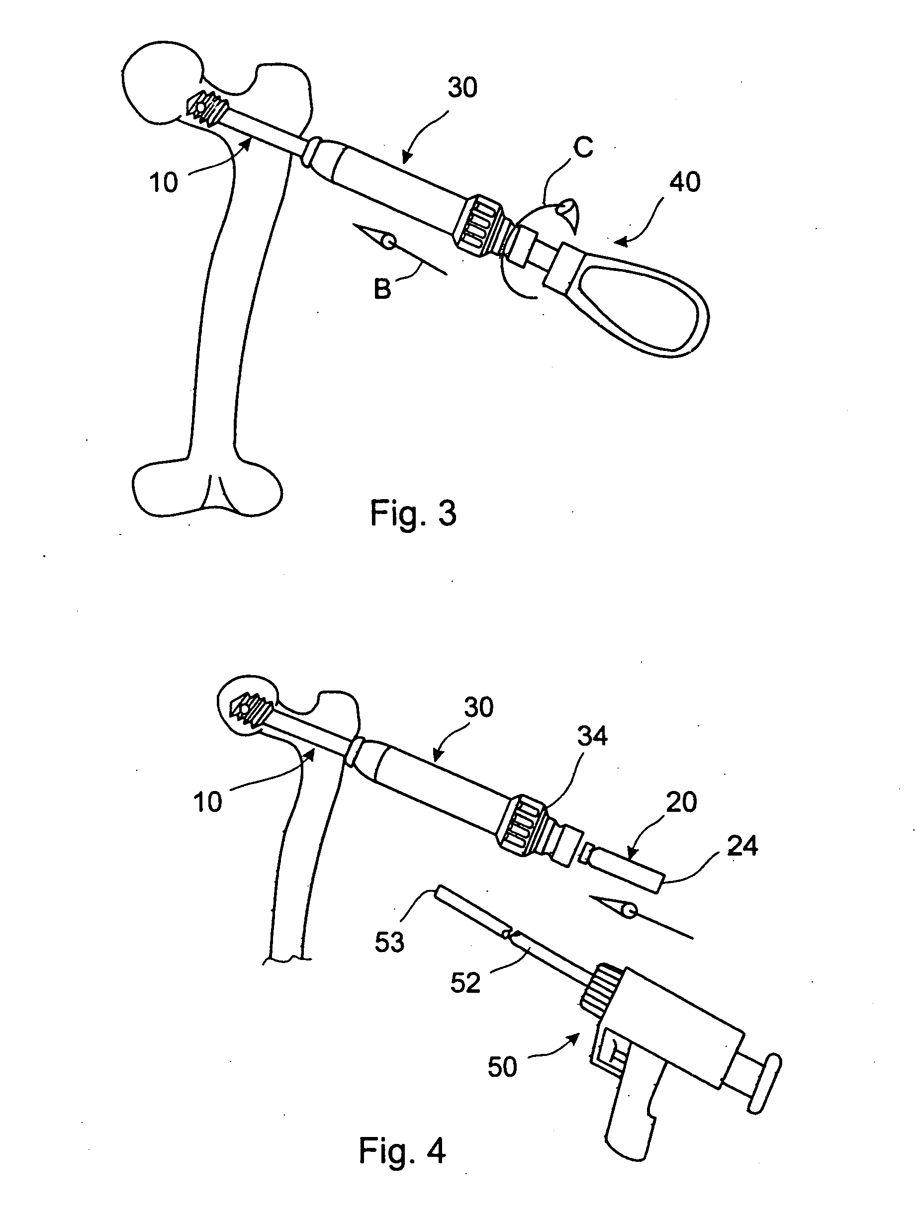
[0042]With the tissue protection sleeve 30 connected with the screw, it may be possible to insert a shaft 41 of a screw driver 40 in the tissue prot...


PUM


Abstract

A screw for fixation of, for example, a fracture having a hollow shaft, a first outer thread and radial openings at its distal end, and a second outer thread and an inner engagement portion at its proximal end. The second outer thread is adapted to engage with a tissue protection sleeve. The inner engagement portion is adapted to fit to a driving end of a driving tool. By way of this, forces in axial or radial direction may be applied to the screw by the sleeve, and forces in rotational direction may be applied by the driving tool. Therefore, the screw can be installed accurately at the intended site in an object.

Description

BACKGROUND OF THE INVENTION[0001]The invention relates in general to sonic fusion technology. It relates more particularly to a screw and a method for the fixation of fractures, particularly bone fractures. The invention relates to a screw for augmenting within a fractured object, to a system including tools to implement the screw into the fractured object, as well as to the use of the mentioned system. The fractured object might be a bone or a wooden or plastic object like furniture.[0002]Known from U.S. Pat. No. 4,653,489 is a system wherein a fixation cement is introduced through a screw into a portion of a bone afflicted by osteoporosis. Femoral neck fractures as well as distal femoral fractures can be fixated by means of this device.[0003]The system in accordance with prior art comprises a screw having a flow cavity, i.e. an axial through bore through with bone cement can be introduced into the portion at the tip of the screw. The bone cement is advanced by a device which is re...

Claims


Application Information

Patent Timeline
IPC IPC(8): A61B17/86A61B17/58
CPCA61B17/68A61B17/7098A61B17/742A61B17/8886A61B17/8822A61B17/8875A61B17/864A61B17/1633A61B17/1668A61B17/8057A61B17/8605A61B17/861A61B17/8685A61B2017/00411A61B2017/8655
Inventor GIERSCH, HELGEDORAWA, KLAUS
Owner STRYKER EURO OPERATIONS HLDG LLC
Why Eureka
Try Eureka