Brake Shoe Support Assembly and Method

a technology for supporting and brake shoes, applied in the direction of brake arrangement with braking members, manufacturing tools, transportation and packaging, etc., can solve the problems of extra maintenance and the connection of ball joints, and achieve the effect of preventing the intrusion of contaminants and preventing the ride-off of the sho

Inactive Publication Date: 2010-10-14
WABTEC HLDG CORP
View PDF51 Cites 11 Cited by
  • Summary
  • Abstract
  • Description
  • Claims
  • Application Information

AI Technical Summary

Benefits of technology

[0010]Generally, as described herein, a brake shoe support assembly, according to embodiments of the invention, is able to track the lateral movement of a wheel, typically a wheel on an axle truck that allows lateral wheel movement. In operation, a flange of the wheel pushes on one side of the brake shoe support assembly pushing it along a pin and compressing a resilient biasing structure. As the wheel returns to the center or neutral position, the compressed resilient biasing structure expands pushing the brake shoe support assembly back to an original position. The resilient biasing structure also minimizes the lateral movement of the brake shoe support assembly down the wheel taper under normal braking loads thus preventing shoe ride-off. The resilient biasing structure may be enclosed in a housing adapted to prevent the intrusion of contaminants.

Problems solved by technology

Such repeated bending tends to crystalize the sides of the brake hanger causing them to create a safety hazard by breaking and permitting the brake rigging to drop on the railway in front of a wheel to possibly cause derailment.
These ball joint connections, however, require extra maintenance, and may themselves be sources of breakage upon the freezing up of the joints, and the like.

Method used


Image

  • Brake Shoe Support Assembly and Method
  • Brake Shoe Support Assembly and Method
  • Brake Shoe Support Assembly and Method

Examples


Embodiment Construction

[0030]For purposes of the description hereinafter, spatial orientation terms, as used, shall relate to the referenced embodiment as it is oriented in the accompanying drawing figures or otherwise described in the following detailed description. However, it is to be understood that the embodiments described hereinafter may assume many alternative variations and embodiments. It is also to be understood that the specific brake shoe holder and railway vehicle braking system incorporating the same as illustrated in the accompanying drawing figures and described herein are simply exemplary and should not be considered as limiting.

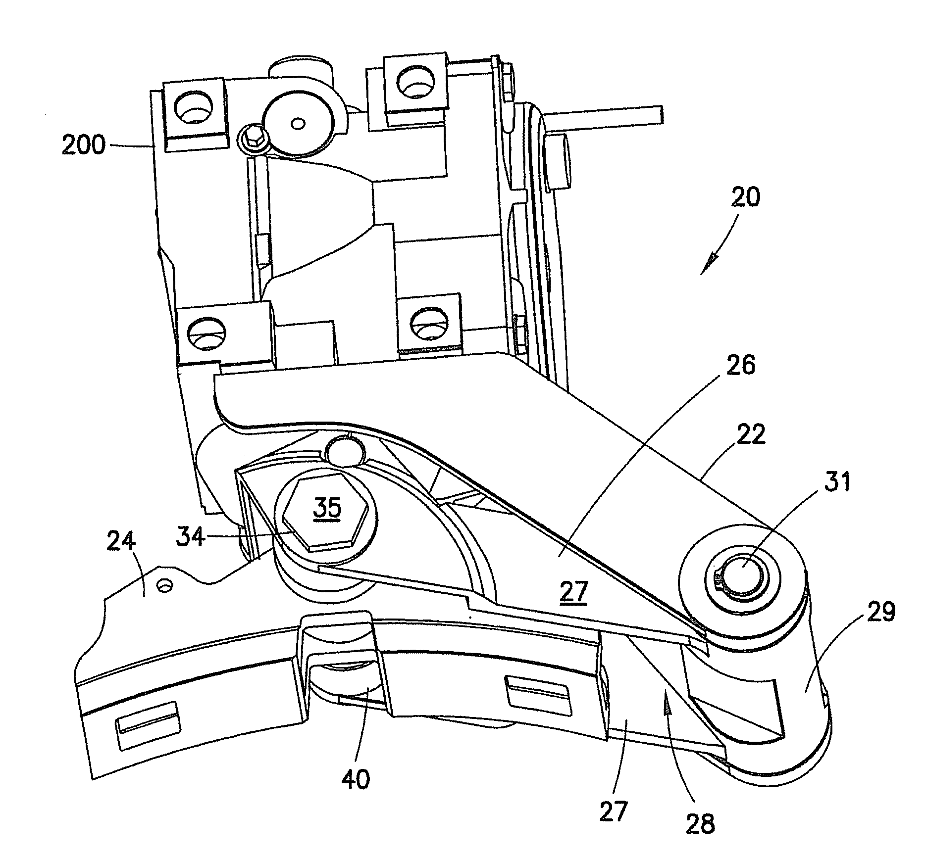
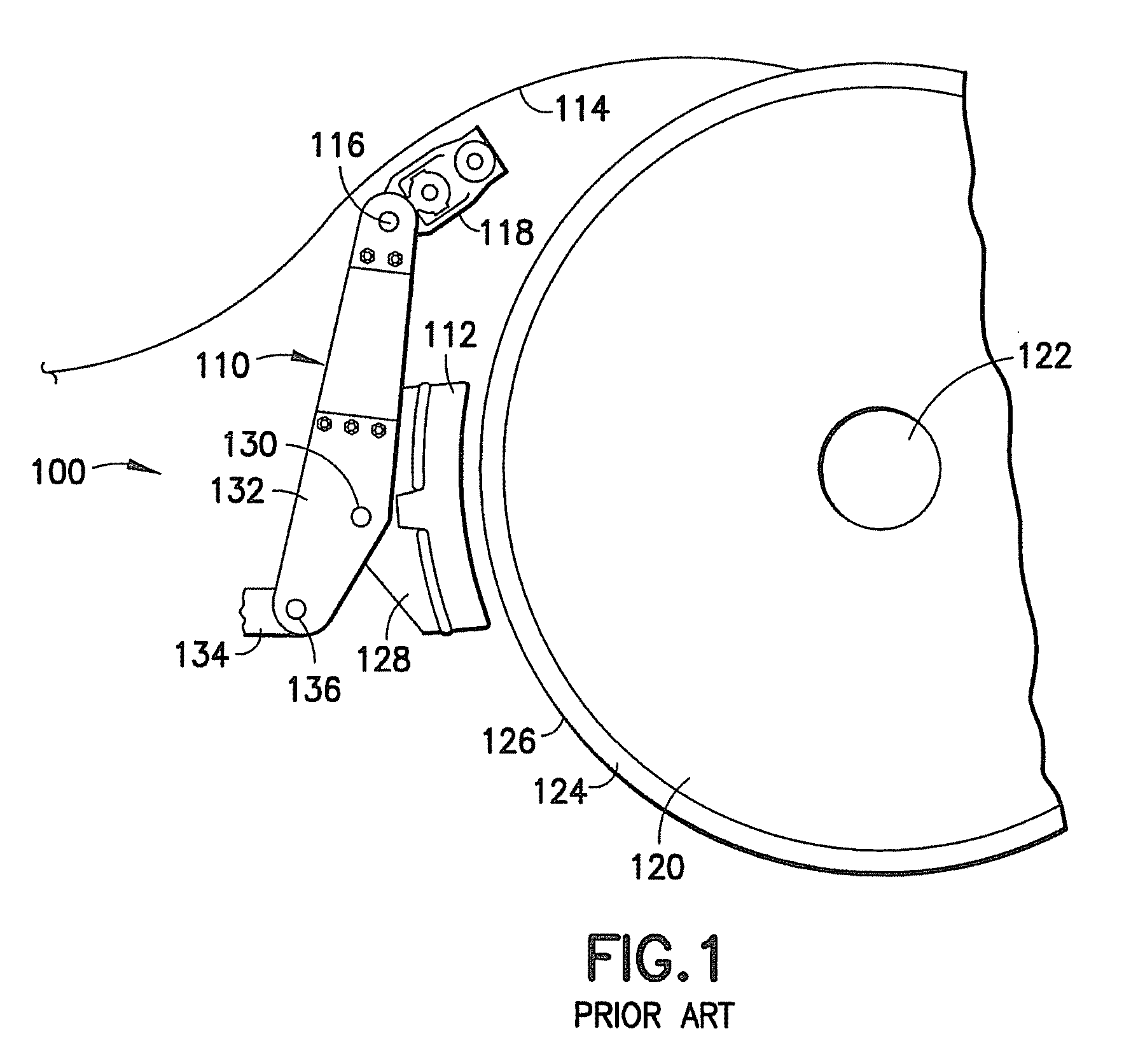
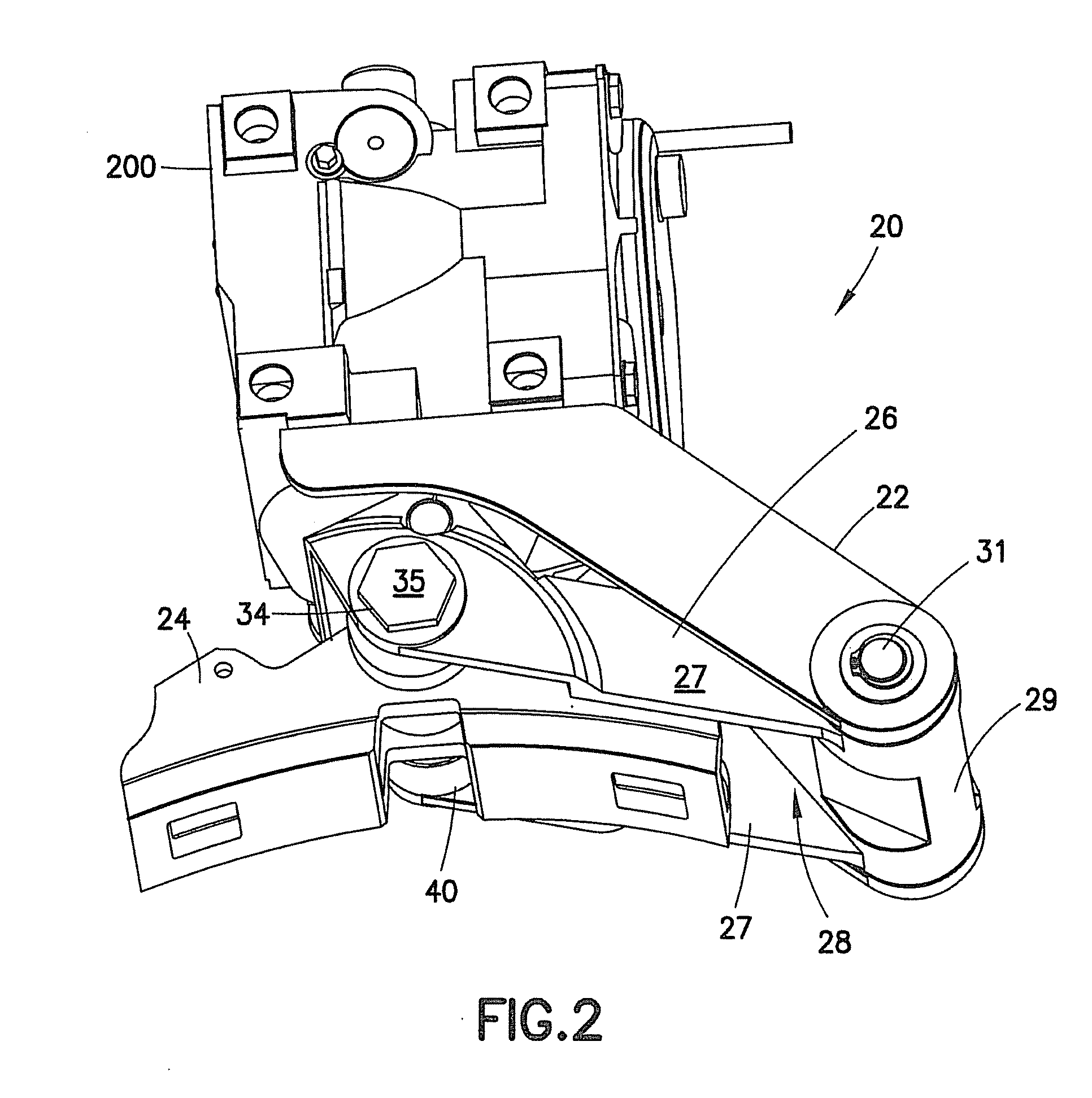
[0031]A brake shoe support assembly 20, as described herein, can be used, for example, in a braking system 100 such as is shown in FIG. 1 (see also U.S. Pat. No. 3,696,892), or be associated with a railway vehicle brake actuator 200 as shown in FIG. 2 as discussed herein. In conventional brake system 100, a brake shoe support 110 is used for suspending a brake sh...


PUM

PropertyMeasurementUnit
resilient biasingaaaaaaaaaa
resilientaaaaaaaaaa
degree of lateral movementaaaaaaaaaa

Abstract

The brake shoe support assembly is able to track the lateral movement of a wheel, typically a wheel on an axle truck that allows lateral wheel movement. In operation, a flange of the wheel pushes on one side of the brake shoe support assembly, pushing it along a pin, and compressing a resilient biasing structure. As the wheel returns to a center or neutral position, the compressed resilient biasing structure expands pushing the brake shoe support assembly back to an original or neutral position. The resilient biasing structure also minimizes the lateral movement of the brake shoe support assembly down the wheel taper under normal braking loads thus preventing shoe ride-off. The resilient biasing structure may be enclosed in a housing adapted to prevent the intrusion of contaminants.

Description

CROSS REFERENCE TO RELATED APPLICATIONS[0001]This application incorporates by reference U.S. Pat. No. 4,406,444 to Bogenshutz and U.S. Pat. No. 3,696,892 to Engle relating, respectively, to a railway vehicle braking system and a brake hanger adapted for use in the rail vehicle braking system.BACKGROUND OF THE INVENTION[0002]1Field of the Invention[0003]The present invention relates to brake shoe supports for railway vehicles and, more particularly, relates to a brake shoe support permitting a degree of lateral movement of an associated brake shoe to track the lateral movement of a wheel on a railway vehicle truck frame.[0004]2. Description of Related Art[0005]It is well known that there is some periodic lateral movement of a railway truck relative to the truck wheels as, for example, the railway vehicle operates in a curved section of track. In certain early patents, brake hangers are disclosed that bend to permit limited lateral movement of the brake shoes during braking relative t...

Claims


Application Information

Patent Timeline
Patent Type & Authority Applications(United States)
IPC IPC(8): B61H13/36B23P19/04
CPCF16D49/16Y10T29/53F16D65/062B61H1/00B61H5/00F16D65/04
Inventor MATHERN, PETER D.MOORE, ROLAND S.
Owner WABTEC HLDG CORP
Why Eureka
Try Eureka