Power transmission device

a transmission device and power technology, applied in the direction of magnetically actuated clutches, clutches, mechanical equipment, etc., can solve the problems of shortened service life impracticality, vibration generated by the power transmission device, etc., to reduce the spring constant of the damper mechanism and reduce the natural frequency

Inactive Publication Date: 2010-10-14
DENSO CORP +1
View PDF10 Cites 33 Cited by
  • Summary
  • Abstract
  • Description
  • Claims
  • Application Information

AI Technical Summary

Benefits of technology

[0011]According to the above aspect of the present invention, the magnetic join portion transmits a rotary driving force from the driving rotor to the driven rotor by a magnetic force, while keeping the predetermined clearance between the driving rotor and the driven rotor, and further acts as a damper mechanism. The power transmission device of the present invention can decrease the spring constant of the damper mechanism without taking into consideration the durability and body size of rubber, elastomer, or the like as compared to a power transmission device with a damper mechanism made of only elastic member, such as rubber or elastomer. As a result, the power transmission device of the present invention can sufficiently reduce the natural frequency as compared to the frequency of vibration generated from the vehicle-mounted rotary device in idling of the vehicle.
[0012]For example, the magnetic join portion may, be configured by permanent magnets arranged in the circumferential direction. More specifically, the maximum rotary driving force transmitted by the magnetic join portion from the driving rotor to the driven rotor is set to not less than 15 Nm and not more than 150 Nm, so that the rotary driving force can be transmitted without problems in practical use by the power transmission device used in a compressor included in a refrigeration cycle of an air conditioner for the vehicle.

Problems solved by technology

The power transmission device is subjected to vibrations generated from a compressor or vehicle-mounted rotary devices other than the compressor.
However, the amount of deformation of rubber or elastomer may become large, and thereby it disadvantageously results in shortened service life of the damper mechanism.
However, the excessively large body of the damper mechanism makes it difficult to apply the damper mechanism to the power transmission device to be mounted on a vehicle, thereby proving impractical.

Method used


Image

  • Power transmission device
  • Power transmission device
  • Power transmission device

Examples


first embodiment

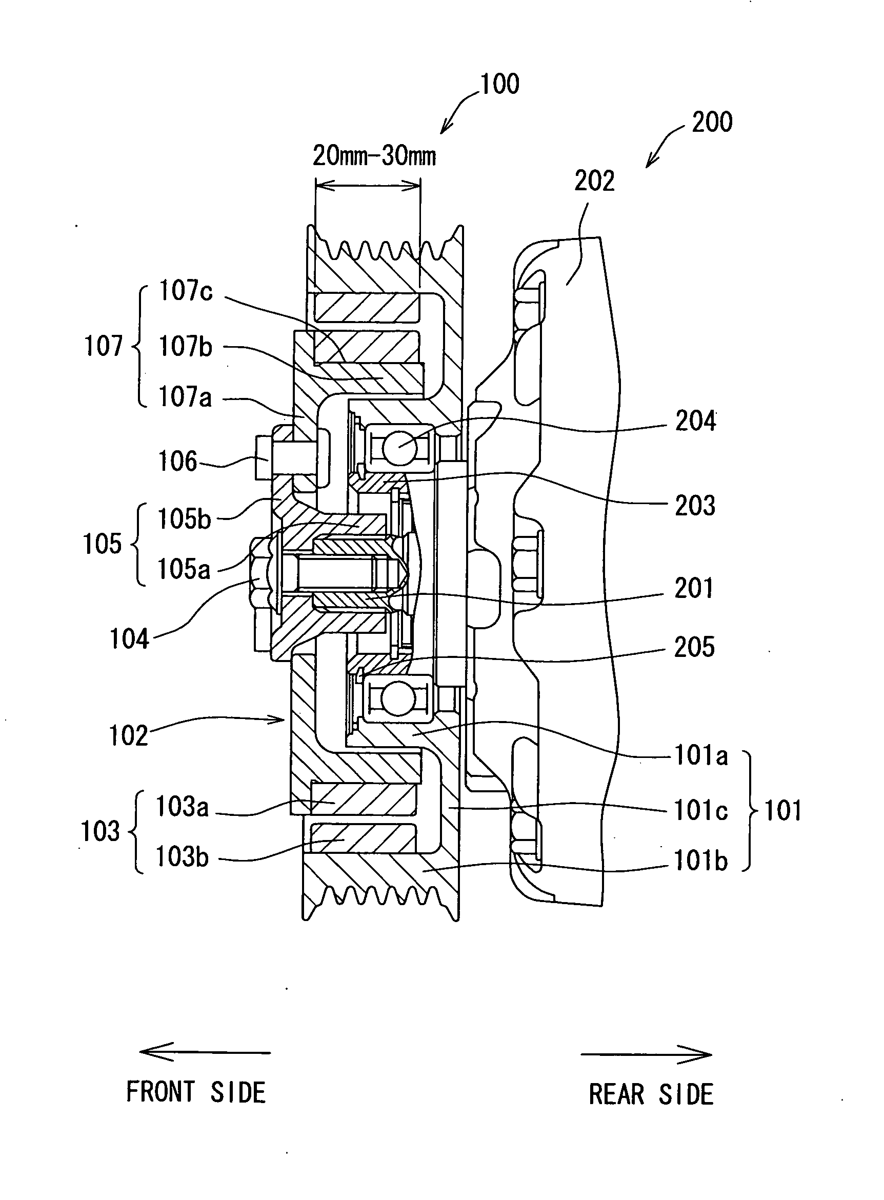
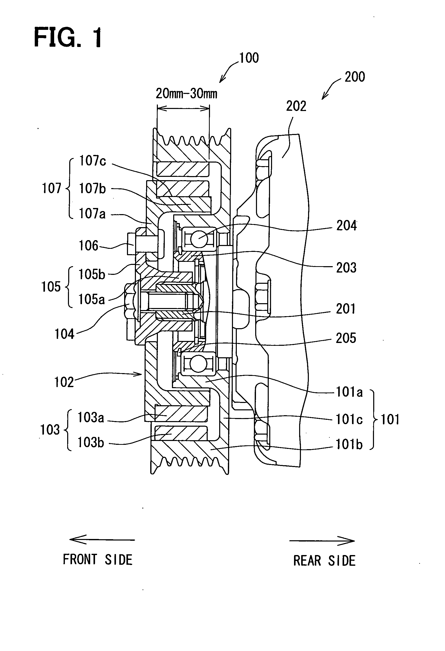
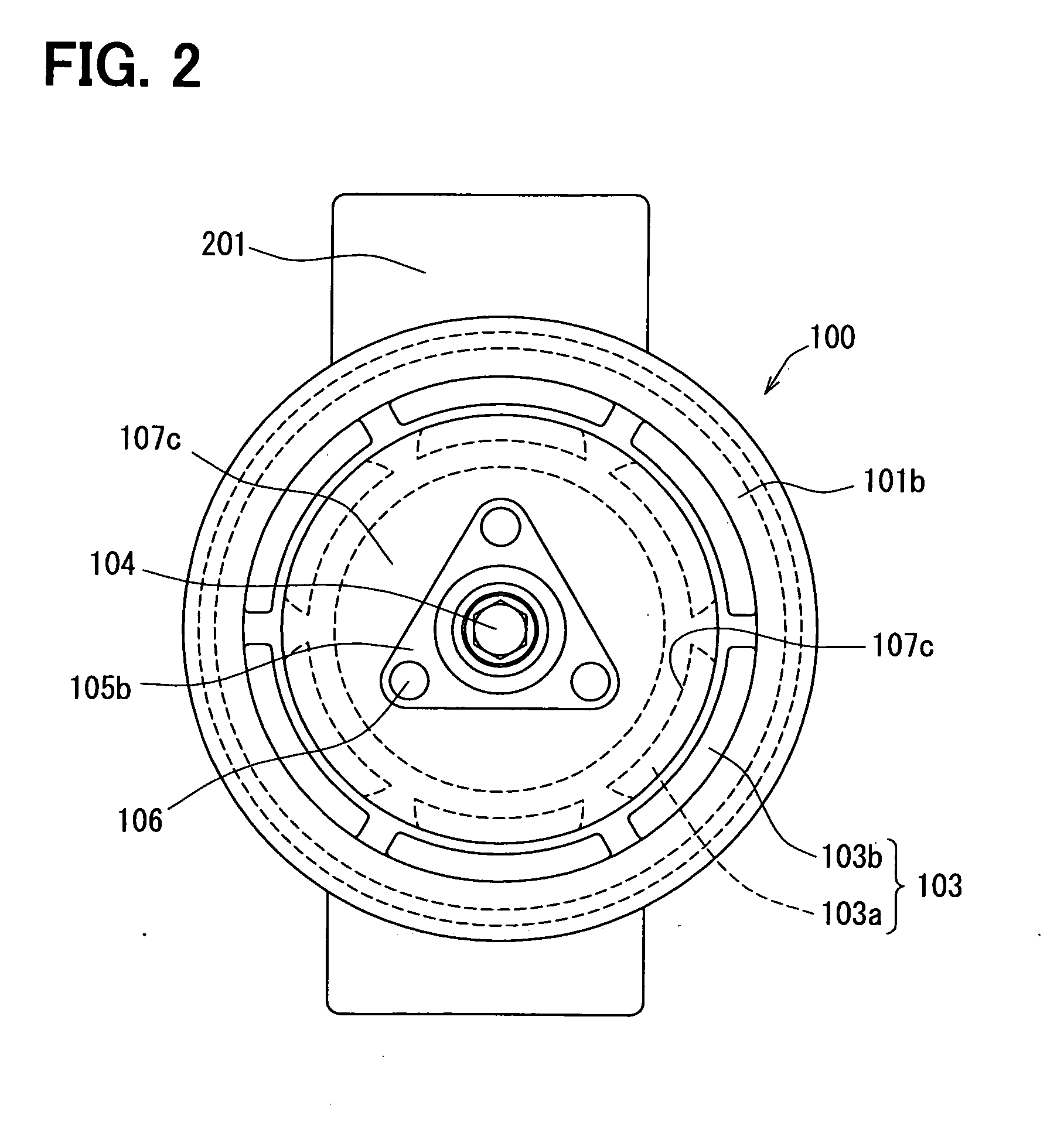
[0023]First, the structure according to a first embodiment of the present invention will be described below with reference to FIGS. 1 and 2. FIG. 1 is a cross-sectional view of a power transmission device 100 in the first embodiment. The power transmission device 100 of the embodiment transmits a driving force from a vehicle-mounted driving source, such as an internal combustion engine (not shown) or a motor for vehicle traveling, to a compressor 200 included in a refrigeration cycle of an air conditioner for a vehicle via a belt (not shown).

[0024]The power transmission device 100 includes a pulley 101 mechanically coupled to the vehicle driving source via the belt, a hub 102 arranged coaxially with the pulley 101 and mechanically coupled to a drive shaft 201 of the compressor 200, and a magnetic join portion 103 disposed in both pulley 101 and hub 102. The magnetic join portion 103 is adapted to transmit a rotary driving force from the pulley 101 to the hub 102 by a magnetic force,...

second embodiment

[0048]Next, the structure according to a second embodiment of the present invention will be described below with reference to FIG. 5. FIG. 5 is a cross-sectional view of a power transmission device 300 in the second embodiment. The second embodiment differs from the first embodiment in arrangement of driven permanent magnets 303a and driving permanent magnets 303b of the magnetic join portion 303. In the following description, the same components as those of the power transmission device 100 of the first embodiment, namely, the compressor 200, the drive shaft 201, the housing 202, the boss 203, the radial bearing 204, the collar 205, the bolt 104, the inner hub 105, and the rivet 106 are designated by the same reference numerals in FIG. 5, and the description thereof will be omitted below.

[0049]A pulley 301 of the embodiment includes an inner ring 301a rotatably supported by the boss 203 of the housing 202 via the radial bearing 204, an outer ring 301b having V-like grooves formed a...

third embodiment

[0053]Although in the above first and second embodiments, the present invention is applied to the pulley as the power transmission device by way of example, the present invention is not limited to the pulley. Alternatively, the present invention may be applied to an electromagnetic clutch as a power transmission device. When the present invention is applied to the electromagnetic clutch, the magnetic join portion is used instead of a rubber damper used in a conventional electromagnetic clutch, like the first and second embodiments.

[0054]Now, a third embodiment of the present invention applied to the electromagnetic clutch will be described below with reference to FIGS. 7 and 8. FIG. 7 is a cross-sectional view of an electromagnetic clutch 400 of the embodiment.

[0055]The electromagnetic clutch 400 includes a stator 401 fixed to a housing 502 of a compressor 500, a rotor 403 rotatably supported by a boss 503 standing from the housing 401 via a radial bearing 504, a hub 404 attached to...


PUM


Abstract

A power transmission device for transmitting a driving force from a vehicle-mounted driving source to a vehicle-mounted rotary device includes a driving rotor mechanically coupled to the vehicle-mounted driving source via a belt, and a driven rotor disposed coaxially with the driving rotor and mechanically coupled to a drive shaft of the vehicle-mounted rotary device. Furthermore, the power transmission device is provided with a magnetic join portion disposed in at least one of the driving rotor and the driven rotor, and the magnetic join portion is adapted to transmit a rotary driving force from the driving rotor to the driven rotor by a magnetic force, while keeping a predetermined clearance between the driving rotor and the driven rotor. Thus, in the power transmission device, a natural frequency can be made much lower than a frequency of vibration generated from the vehicle-mounted rotary device in idling of a vehicle.

Description

CROSS REFERENCE TO RELATED APPLICATION[0001]This application is based on Japanese Patent Applications No. 2007-279177 filed on Oct. 26, 2007 and No. 2008-268420 filed on Oct. 17, 2008, the contents of which are incorporated herein by reference in its entirety.TECHNICAL FIELD[0002]The present invention relates to a power transmission device for transmitting power from a driving source to a vehicle-mounted rotary device.BACKGROUND ART[0003]Conventionally, power transmission devices for transmitting power from a driving source to a vehicle-mounted rotary device, such as a compressor for a vehicle air conditioner, include a damper mechanism made of an elastic member, such as rubber or elastomer, for attenuating vibration of the vehicle-mounted rotary device due to variations in load torque (as disclosed in, for example, JP 2005-201433A).[0004]The power transmission device is subjected to vibrations generated from a compressor or vehicle-mounted rotary devices other than the compressor. ...

Claims


Application Information

Patent Timeline
Patent Type & Authority Applications(United States)
IPC IPC(8): H02K49/06
CPCF16D27/01F16D27/112H02K49/108F16H55/36H02K49/106F16F15/18
Inventor UEDA, MOTOHIKOSAKAI, TAKUOKISHITA, HIROSHIOHNO, YUICHI
Owner DENSO CORP
Why Eureka
Try Eureka