
Rotation-responsive type one-way clutch

a one-way clutch, rotation-responsive technology, applied in the direction of clutches, mechanical actuated clutches, freewheel clutches, etc., can solve the problems of auxiliary rollers being caught in the elongated hole, the necessary number of components becoming larger, and the difficulty in obtaining a desired dimensional accuracy of the one-way clutch, etc., to achieve the effect of reducing the number of necessary components, reducing the constant of the spring, and reducing the number of necessary

Active Publication Date: 2006-01-05
NSK WARNER
View PDF3 Cites 4 Cited by
  • Summary
  • Abstract
  • Description
  • Claims
  • Application Information

AI Technical Summary

Benefits of technology

[0011] In order to solve the above-mentioned problems, an object of the present invention is to provide a rotation-responsive type one-way clutch which can reduce the number of necessary components, which is inexpensive, and which can decrease a spring constant, which can easily obtain dimensional accuracy, which can prevent a weight member from being caught, which can be stably operated without an urging spring displacing diametrically outward, and which has a configuration that can be designed in a space saving manner.
[0014] With the provision of the guide means for preventing the urging spring from displacing diametrically outward, there can be provided a rotation-responsive type one-clutch which can reduce the number of necessary components, which is inexpensive, which can easily obtain dimensional accuracy, which can prevent a weight member from being caught, which can be stably operated without the urging spring from displacing diametrically outward, and which has such a configuration that a rotation-responsive type one way clutch can be designed in a space saving manner.

Problems solved by technology

However, since an elongated hole which defines an operating range of the auxiliary roller is formed in a component other than the inner race, it is difficult to obtain a desired dimensional accuracy for the one-way clutch, and the necessary number of components becomes larger.
Further, there would be such a risk that the auxiliary roller is caught in the elongated hole.
Thus, parts such as a plate and an cantilever piece are required while a space for accommodating therein a spring is also required, and accordingly, it is limited to decrease the diameter of the one-way clutch.
However, even with this configuration, there would be caused such a risk that the urging spring displaces during operation, diametrically outward, that is, toward the outer race, and then comes off.

Method used


Image

  • Rotation-responsive type one-way clutch
  • Rotation-responsive type one-way clutch
  • Rotation-responsive type one-way clutch

Examples


Embodiment Construction

[0021] Explanation will be hereinbelow made of embodiments of the present invention with reference to the accompanying drawings in which like reference numeral denotes like parts.

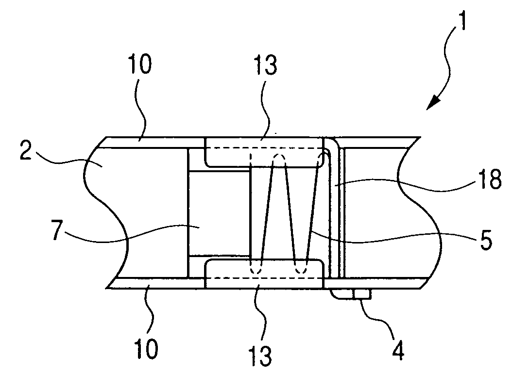
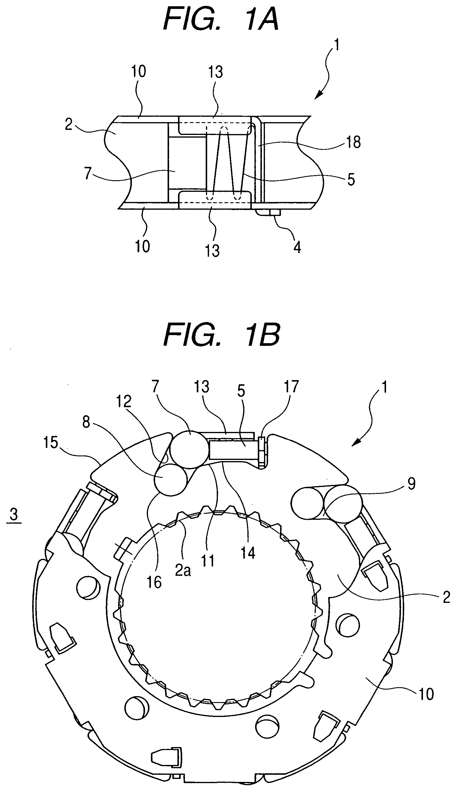
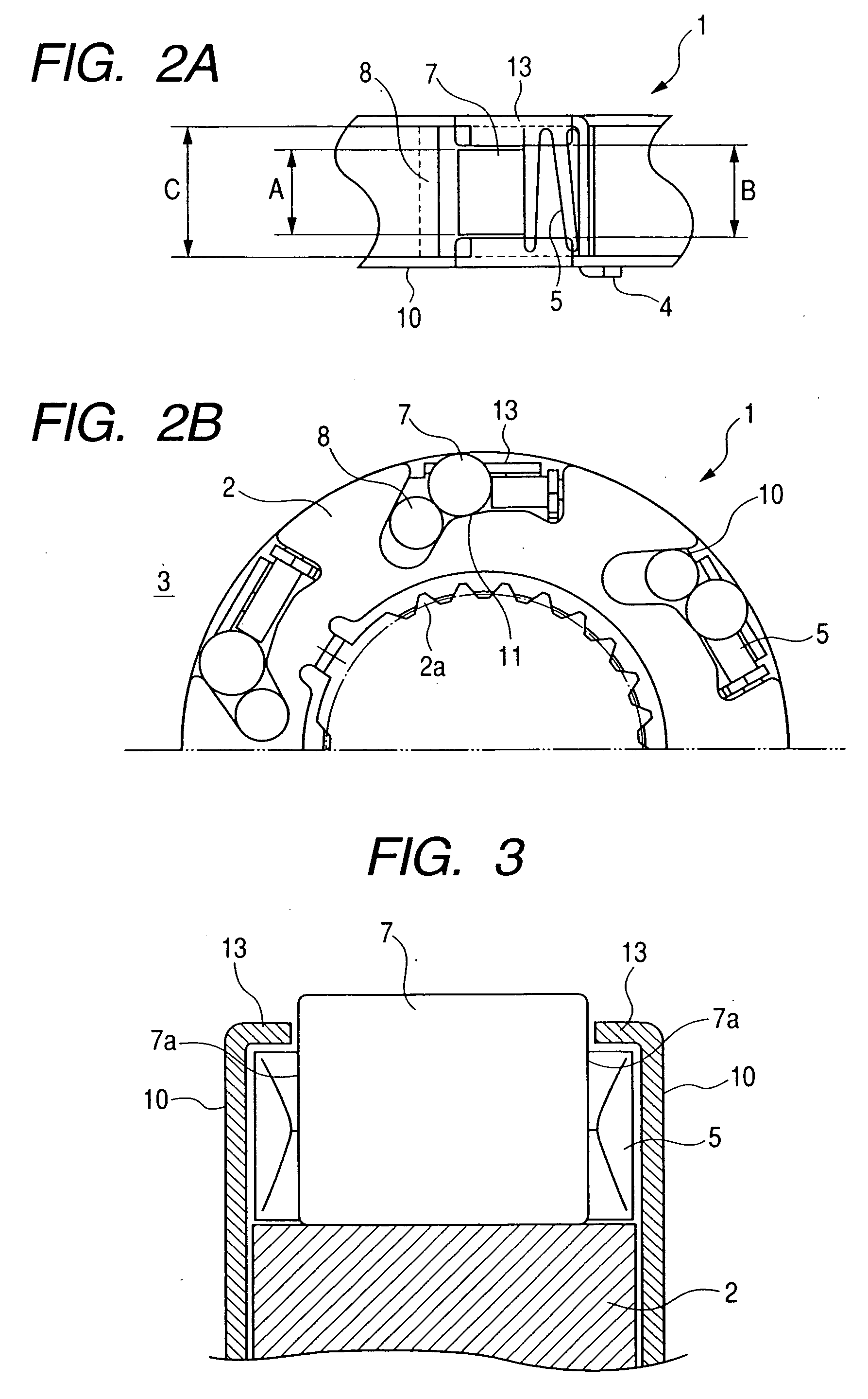
[0022]FIGS. 1A and 1B are a partial top view and a partly broken front view illustrating a rotation-responsive type one-way clutch (which will be hereinbelow sometimes referred to as “one-way clutch” for the sake of convenience in explanation) in an embodiment of the present invention in an disengaged condition in which the one-way clutch 1 slips.

[0023] Referring to FIG. 1B, the one-way clutch 1 is composed of an inner race 2 having an inner peripheral surface in which splines 2a are formed and serving as a hollow shaft fitted on a drive shaft (which is not shown), and an outer race 3 which is arranged radially outward from and concentric with the inner race 2, and which is rotatable, relative to the inner race 2. The inner race 2 has an outer peripheral portion formed therein with a plurality of pockets ...


PUM


Abstract

A rotation-responsive type one-way clutch comprises an outer race having a cylindrical inner peripheral surface, an inner race having a cam surface, a rolling element for transmitting a torque between the outer and inner races, an urging spring for urging the rolling element, a weight member adapted to be exerted thereto with a centrifugal force, for pressing the rolling element in an engaging direction while overcoming an urging force of the urging spring, and a guide means for preventing the urging spring from displacing radially outward.

Description

BACKGROUND OF THE INVENTION [0001] 1. Field of the Invention [0002] The present invention relates to a rotation-responsive type one-way clutch which is used in a motor-cycle, a snow mobile or the like, and which exhibits a one-way clutch function when a rotational speed becomes not less than a predetermined speed. [0003] 2. Description of the Related Art [0004] In general, a one-way clutch is composed of an outer race and an inner race which are rotated relative to each other, a sprag or a roller for transmitting a torque between the outer race and the inner race, which is adapted to be engaged with a cam surface formed on a raceway surface of the inner race or the outer race so as to transmit a torque in only one direction. Incidentally, this clutch slips in the other direction. [0005] There has been known a one-way clutch, as an example of the above-mentioned one-way clutch, wherein the roller is set in a pocket (recess) formed in the inner race or the outer race, and locks the ro...

Claims


Application Information

Patent Timeline
Patent Type & Authority Applications(United States)
IPC IPC(8): F16D41/064
CPCF16D41/066
Inventor MURAMATSU, KAZUHIKO
Owner NSK WARNER
Learn More