Unlock instant, AI-driven research and patent intelligence for your innovation.

Gate drive circuit and driving method thereof

a driving circuit and gate technology, applied in the direction of digital storage, instruments, computing, etc., can solve the problems of increasing manufacturing costs, and achieve the effect of easy switching

Active Publication Date: 2010-10-14
HANNSTAR DISPLAY CORPORATION
View PDF5 Cites 6 Cited by
  • Summary
  • Abstract
  • Description
  • Claims
  • Application Information

AI Technical Summary

Benefits of technology

The present invention provides a gate driving circuit and a driving method that have a symmetric circuit structure and can be reversed in driving direction by reversing the sequence of clock signals and exchanging the scan start and end signals. This allows for easy switching between forward and backward drive modes. The circuit includes a plurality of cascaded drive units sequentially outputting an output signal and includes a first-stage drive unit and a last-stage drive unit that receive a scan start or scan end signal. The driving direction of the circuit can be reversed by reversing the sequence of clock signals and exchanging the scan start and end signals. The technical effect of the invention is to provide a flexible and efficient gate driving circuit that can be easily switched between forward and backward drive modes.

Problems solved by technology

However, the number of the source driving circuits 92 and the gate driving circuits 93 will be increased at the same time thereby increasing the manufacturing cost.
Accompanying with the increase of the applicable range of the liquid crystal display, gate driver ICs with reversible operation function have been proposed commercially, but conventional integrated gate driving circuits do not have this function.

Method used


Image

  • Gate drive circuit and driving method thereof
  • Gate drive circuit and driving method thereof
  • Gate drive circuit and driving method thereof

Examples


Embodiment Construction

[0031]It should be noticed that, wherever possible, the same reference numbers will be used throughout the drawings to refer to the same or like parts.

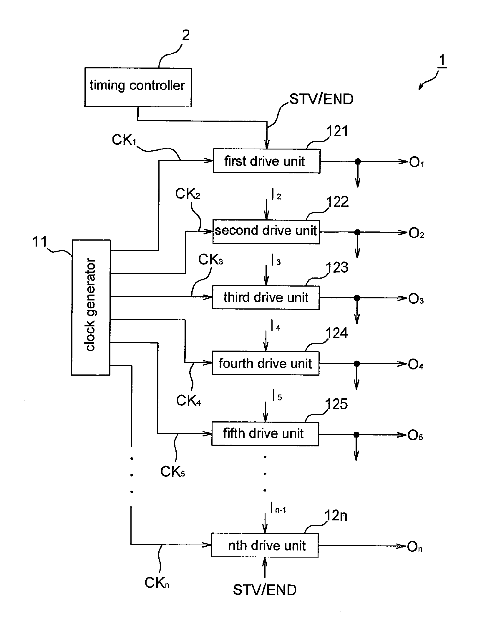
[0032]Please refer to FIG. 3, it shows a gate driving circuit 1 in accordance with an embodiment of the present invention. The gate driving circuit 1 includes a clock generator 11 configured to generate a plurality of sequential clock signals and a plurality of cascaded drive units, e.g. a first drive unit 121, a second drive unit 122, a third drive unit 123, a fourth drive unit 124, a fifth drive unit 125 and an nth drive unit 12n. The first drive unit 121 may be served as a first-stage drive unit or a last-stage drive unit of the gate driving circuit 1, and receives at least one clock signal CK1 and a scan start signal STV (i.e. the input signal of the first-stage drive unit) or a scan end signal END (i.e. the input signal of the last-stage drive unit), and outputs a first output signal O1, wherein the first output signal O1 is simu...


PUM


Abstract

A gate driving circuit receives a plurality of clock signals in a sequence and includes a plurality of cascaded drive units sequentially outputting an output signal, wherein a first-stage drive unit of the gate driving circuit receives a scan start signal or a scan end signal while a last-stage drive unit thereof receives a scan end signal or a scan start signal; wherein a driving direction of the gate driving circuit is reversed by reversing the sequence of the clock signals and exchanging the scan start signal and the scan end signal. The present invention further provides a driving method of a gate driving circuit.

Description

CROSS REFERENCE TO RELATED APPLICATION [0001]This application claims the priority benefit of Taiwan Patent Application Serial Number 098111628, filed on Apr. 8, 2009, the full disclosure of which is incorporated herein by reference.BACKGROUND [0002]1. Field of the Invention[0003]This invention generally relates to a driving circuit and a driving method thereof and, more particularly, to a bidirectional integrated gate driving circuit and a driving method thereof.[0004]2. Description of the Related Art[0005]Referring to FIG. 1, a liquid crystal display 9 normally includes a pixel matrix 91, a plurality of source driving circuits 92 and a plurality of gate driving circuits 93. Generally speaking, the quality of images shown by the liquid crystal display 9 may be improved by increasing the resolution of the liquid crystal display 9. However, the number of the source driving circuits 92 and the gate driving circuits 93 will be increased at the same time thereby increasing the manufactur...

Claims


Application Information

Patent Timeline
Patent Type & Authority Applications(United States)
IPC IPC(8): G09G5/00
CPCG09G3/3677G11C19/28G09G2310/0283
Inventor CHANG, HSIEN CHENGCHEN, YAN JOU
Owner HANNSTAR DISPLAY CORPORATION