Multi-user autostereoscopic display

Inactive Publication Date: 2010-10-14
SURMAN PHILIP
View PDF3 Cites 37 Cited by
  • Summary
  • Abstract
  • Description
  • Claims
  • Application Information

AI Technical Summary

Benefits of technology

[0017]The present invention provides an improved display, which is a projection display which includes different light configuration means which provides different sets of vert

Problems solved by technology

Broadcast television is probably the largest potential application, however the requirements of a television system are complex and few, if any, existing display systems can meet these requirements.
Such a system is more complex than those intended for single viewers proposed, for example, for computer monitor or arcade game applications.
Prior art systems which

Method used


Image

  • Multi-user autostereoscopic display
  • Multi-user autostereoscopic display
  • Multi-user autostereoscopic display

Examples


Embodiment Construction

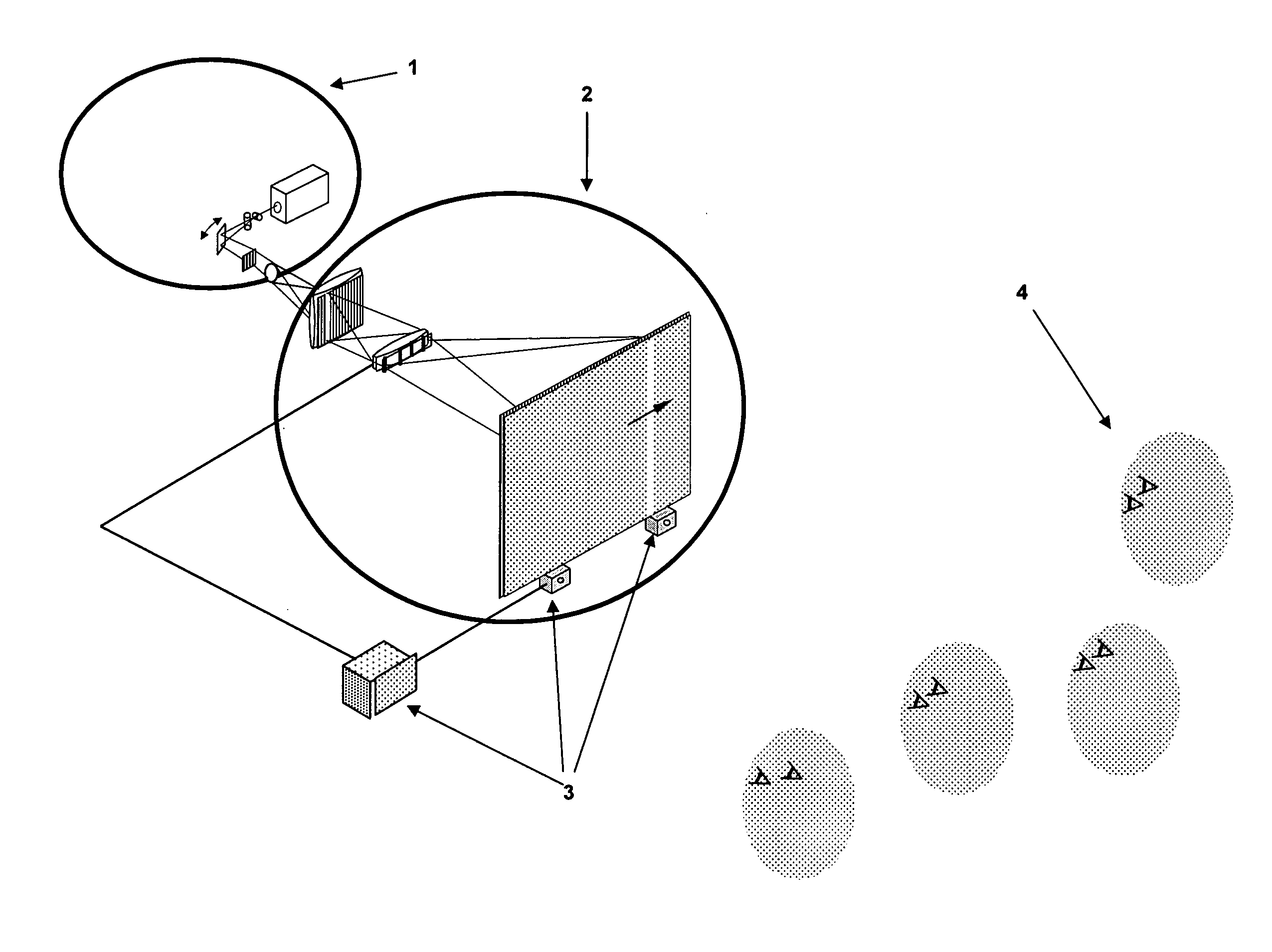
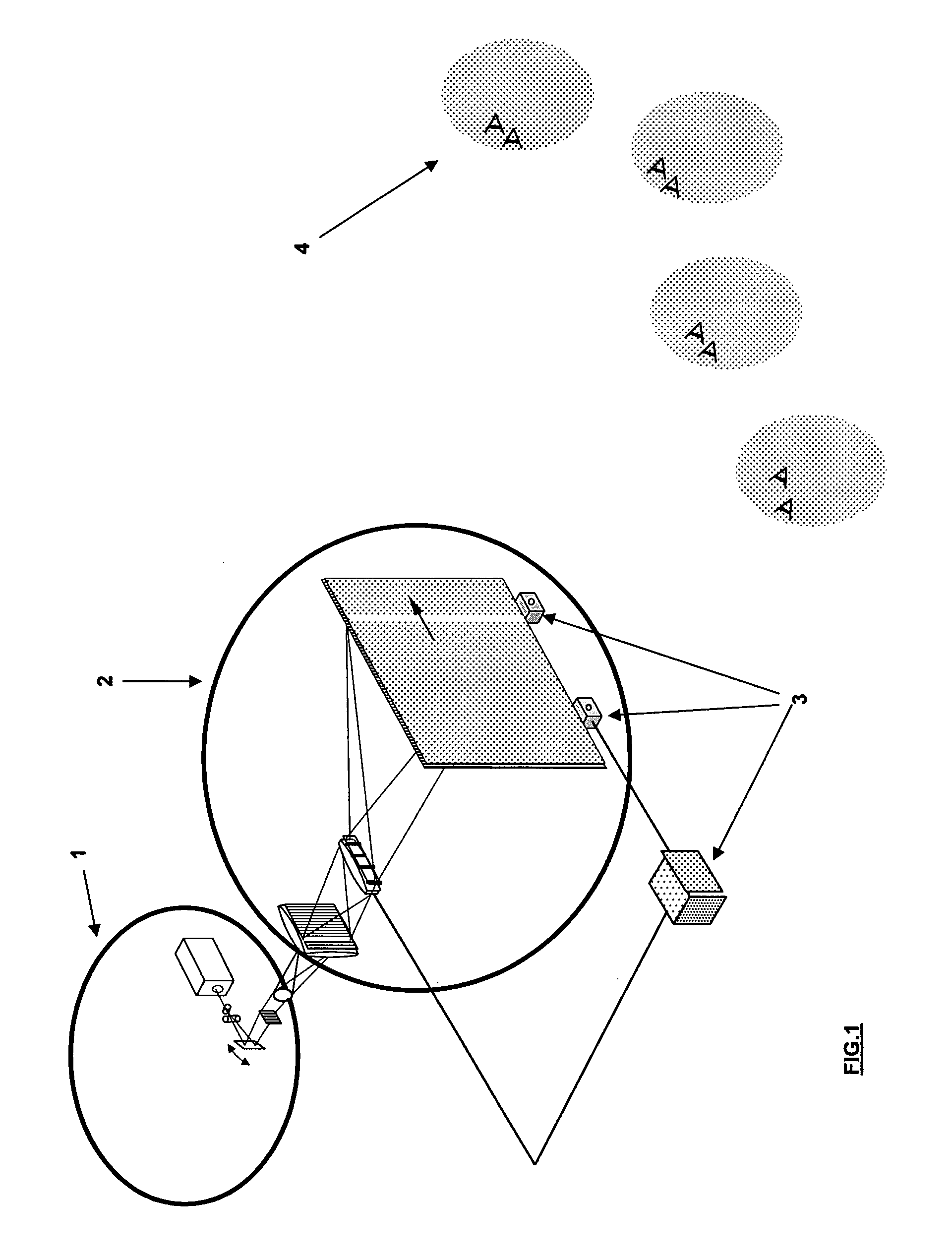
[0038]In accordance with embodiments of the invention, the display operates by producing regions in the viewing field referred to as exit pupils where a viewer's eye can see the image on the screen that is intended for that eye. FIG. 1 is a schematic diagram of the display, comprised of image generation means 1, light configuration means 2, and a pupil position tracker 3. The image generation means 1 may be comprised of a plurality of different components which will be discussed in turn when describing different embodiments of the present invention. The image generation means 1 generates images which are observable by one or more selected viewer's eyes 4 when positioned at an exit pupil. The light configuration means 2 is used to manipulate the propagating beams of light so as to steer exit pupils to positions substantially coincident with the one or more viewer's eyes 4 in the viewing field. In preferred embodiments the light configuration means 2 is used to provide a plurality of ...


PUM


Abstract

A display apparatus for projecting images towards eyes of at least one viewer selectively when said eyes are spaced horizontally within a viewing field, said apparatus comprising: transmitting means for transmitting light; image generation means for generating different images, the image generation means being capable of generating image parts in a plurality of different vertical image areas; and light configuration means for configuring said transmitted light to provide a plurality of sets of vertical light configurations, the different configurations in each set being selectable to provide different emergent light characteristics for a vertical image area which is common to each configuration in a set and which is different for each set, whereby said different images are projected by said apparatus to coincide with one or more eyes selected from the eyes of each of the one or more viewers, and not one or more other eyes of the viewers.

Description

FIELD OF THE INVENTION[0001]The present invention relates to the field of autostereoscopic display devices where viewers who do not have to wear special glasses can see three-dimensional (3D) images. In particular, but not exclusively the invention relates to supplying stereo images to several viewers who have a relatively high degree of freedom of movement.BACKGROUND OF THE INVENTION[0002]Prior art 3D displays have been described in a large variety of publications, including “New Autostereoscopic Display System”, Ezra, Woodgate, Omar, Holliman, Harrold and Shapiro (1995), SPIE Proceedings “Stereoscopic Displays and Virtual Reality Systems H” Vol. 2409, pp 31-40; “Retroreflective Screens and their Application to Autostereoscopic Displays” Harman, SPIE Proceedings “Stereoscopic Displays and Virtual Reality Systems IV”, Vol. 3012, pp 145-153; “Stereoscopic Display Employing Head-position Tracking using Large Format Lenses”, Hattori, (1993), SPIE Proceedings “Stereoscopic Displays and ...

Claims


Application Information

Patent Timeline
IPC IPC(8): H04N13/04
CPCG02B27/225H04N13/0418H04N13/0475H04N13/047H04N13/0459H04N13/32H04N13/368H04N13/363H04N13/373
Inventor SURMAN, PHILIP
Owner SURMAN PHILIP
Why Eureka
Try Eureka