Video laryngoscope system and devices

a laryngoscope and video technology, applied in the field of airway management and upper airway examination, can solve the problems of death or serious injury, intubation is a complex process, and the patient is prone to myriad possible injuries,

Inactive Publication Date: 2010-10-14
VERATHON
View PDF7 Cites 97 Cited by
  • Summary
  • Abstract
  • Description
  • Claims
  • Application Information

AI Technical Summary

Problems solved by technology

It is well known that failure to intubate when required can lead to death or serious injury.
Intubation is a complex process which presents numerous challenges, as well as myriad possible injuries to the

Method used


Image

  • Video laryngoscope system and devices
  • Video laryngoscope system and devices
  • Video laryngoscope system and devices

Examples


Embodiment Construction

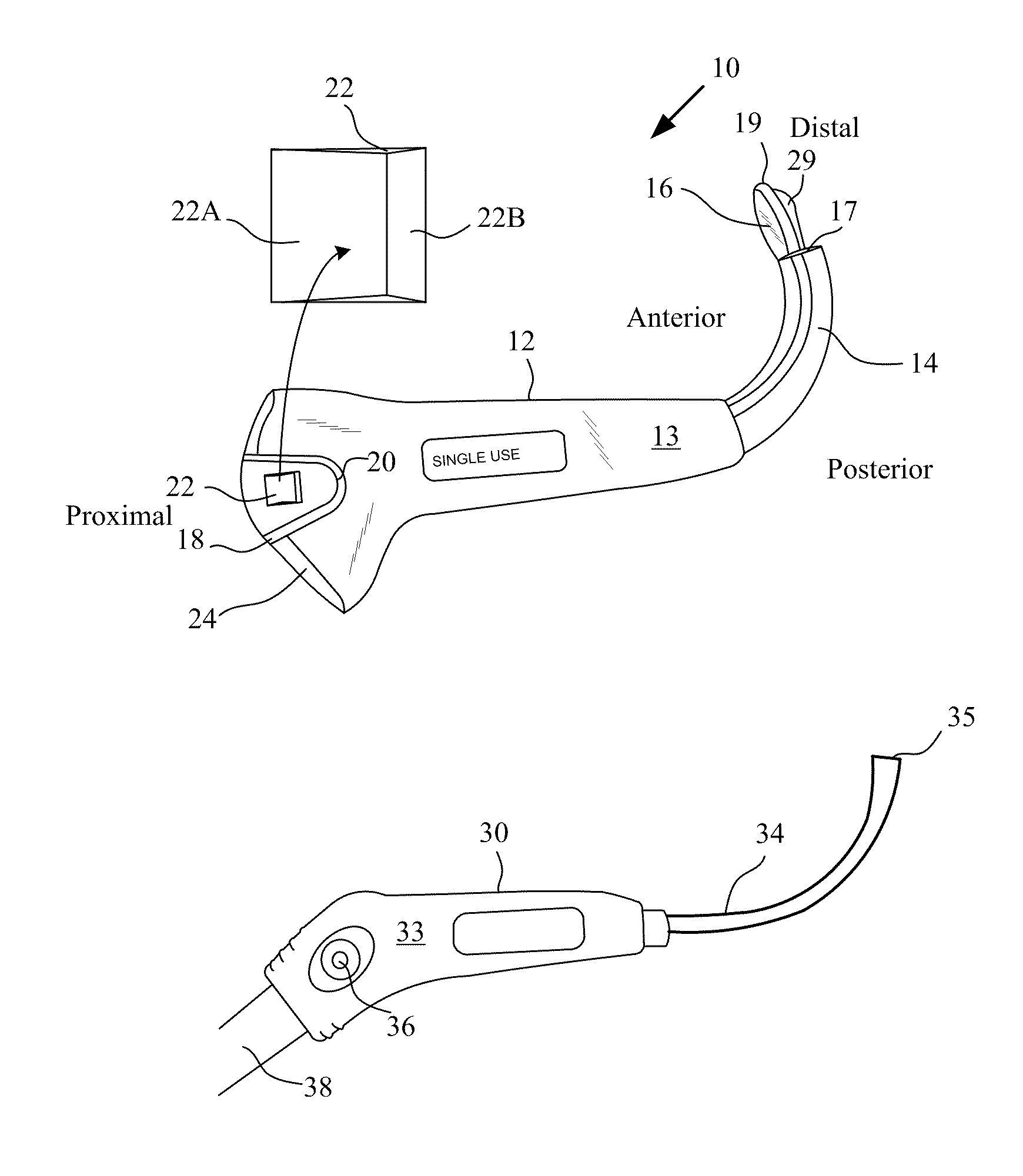
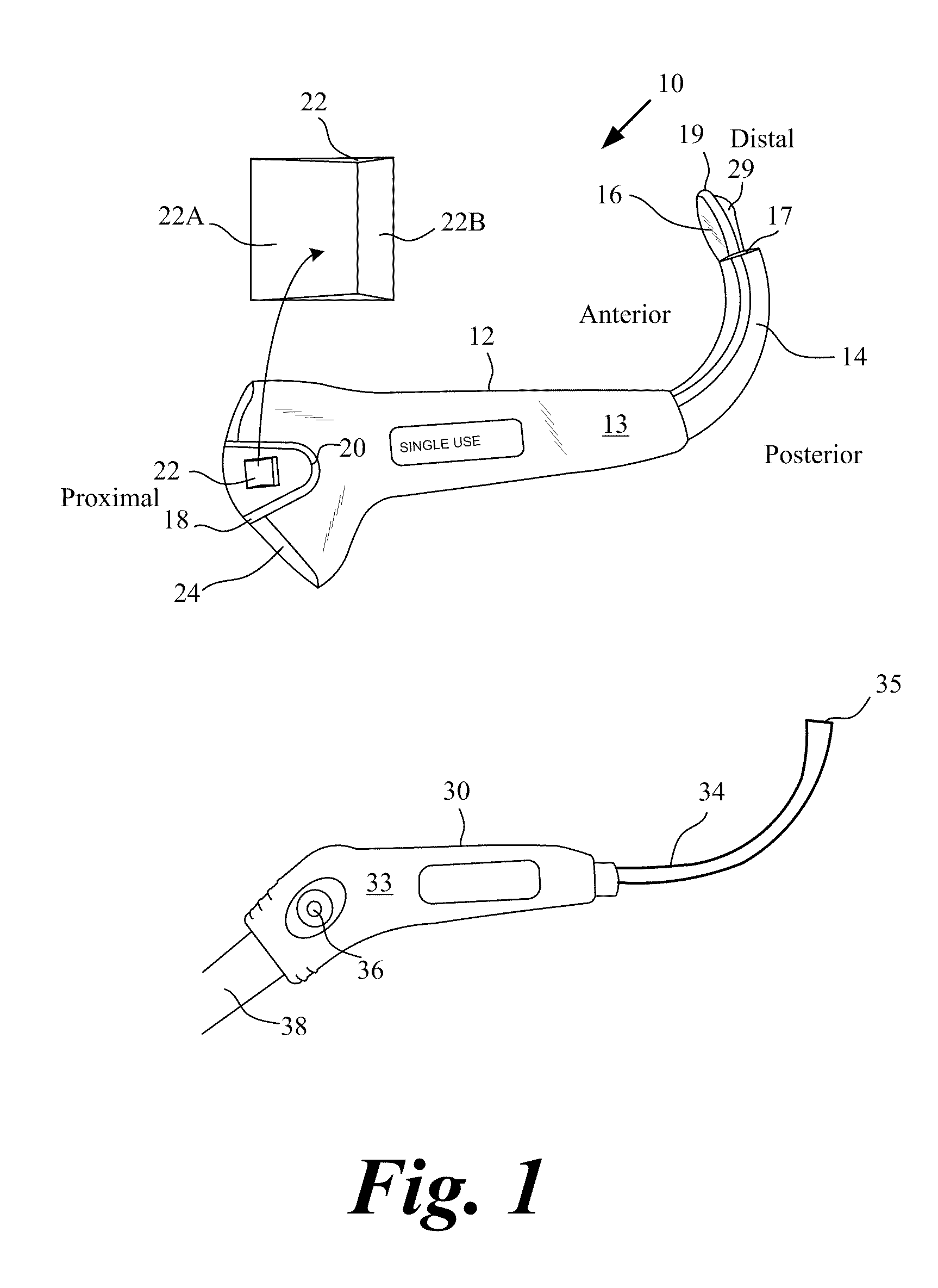
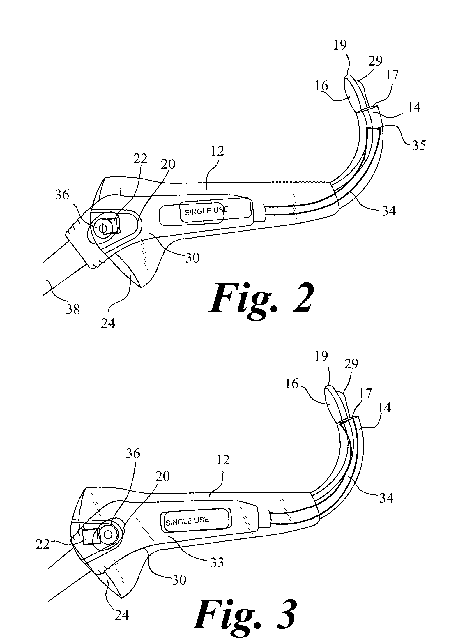
[0032]Several embodiments of a video-based intubation laryngoscope and system are described that allow for examination of the upper airway and intubation. The system employs video laryngoscope embodiments configured to view a patient's glottis, reposition the patient's epiglottis, view the glottic aperture and convey video images of the patient's upper airway anatomy including the glottis and / or glottic aperture and surrounding area to a video monitor viewable by the laryngoscope user. An endotracheal tube (ETT) is placed within the patient's oral cavity and its position relative to the patient's GA is noted from the images presented on the video monitor. Based on video images displayed on the monitor, the ETT is advanced into the trachea through the patient's glottic aperture via an accessory stylet located within the lumen of the ETT.

[0033]Embodiments of the laryngoscope include substantially clear housings or sheaths intended for single use into which a video baton is inserted. T...


PUM


Abstract

An embodiment encompassing reusable video laryngoscopes that are insertable into transparent or non-transparent disposable sheaths having clear optically clear viewing windows that receive contact with camera lens. The reusable video laryngoscopes are configured to be detachably secured by locking tabs located in the transparent or non-transparent disposable sheaths with complementary shaped posts and ledges of the video laryngoscopes. The video laryngoscopes that are secured into the transparent or non-transparent disposable sheaths may be inserted into the patient's mouth to provide clear camera viewing through the optically clear window ports of the transparent or non-transparent disposable sheaths to allow endotracheal procedures to be undertaken. The transparent or non-transparent disposable sheaths are sterilizable and may be used just once for a given patient. The video laryngoscopes in the form of a baton are detachably removeable from the disposable sheath exposed to a patient.

Description

CROSS REFERENCES TO RELATED APPLICATIONS[0001]The application claims priority to and incorporates by reference in their entirety U.S. Provisional Patent Applications Nos. 61 / 319,835 filed Mar. 31, 2010; 61 / 261,739 filed Nov. 16, 2009; and 61 / 169,446 filed Apr. 14, 2009. This application also incorporates by reference in their entirety U.S. Pat. No. 6,142,144 filed Apr. 1, 1998 and its U.S. Provisional Patent Application Nos. 60 / 074,355 filed Feb. 10, 1998 and 60 / 067,205 filed Dec. 7, 1997; U.S. Pat. No. 6,543,447 filed Dec. 6, 2000 and its U.S. patent application Ser. No. 09 / 704,507 filed Nov. 2, 2007 and 09 / 060,891 filed Apr. 15, 1998; and U.S. Pat. No. 6,655,377 filed Jan. 30, 2003 and its U.S. patent application Ser. No. 09 / 732,129 filed Dec. 6, 2000 and 09 / 704,507 filed Nov. 2, 2000, and U.S. Provisional Patent Application Nos. 60 / 352,283 filed Jan. 30, 2002; 60 / 223,330 filed Aug. 7, 2000; 60 / 168,711 filed Dec. 6, 1999; 60 / 074,355 filed Feb. 10, 1998, and 60 / 067,205 filed Dec. 1...

Claims


Application Information

Patent Timeline
IPC IPC(8): A61B1/267
CPCA61B1/00103A61B1/00135A61M16/0488A61B1/06A61B1/267A61B1/00142A61M16/0495A61M16/0486A61M16/0484
Inventor PACEY, JOHN ALLENVISSER, MITCHELLYAZDI, REZA AHMADIANKIM, YONGKOOK
Owner VERATHON
Why Eureka
Try Eureka