
Car-top tent

a car-top tent and tent technology, applied in the field of car-top tent structure, can solve the problems of undesired safety problems of users who fall off the ladder, extreme danger in a wild area, increase the consumption of fuel, etc., and achieve the effect of eliminating the potential risk of undesired accidents and enhancing safety

Inactive Publication Date: 2010-10-21
CHIU CHAO HSIUNG
View PDF10 Cites 24 Cited by
  • Summary
  • Abstract
  • Description
  • Claims
  • Application Information

AI Technical Summary

Benefits of technology

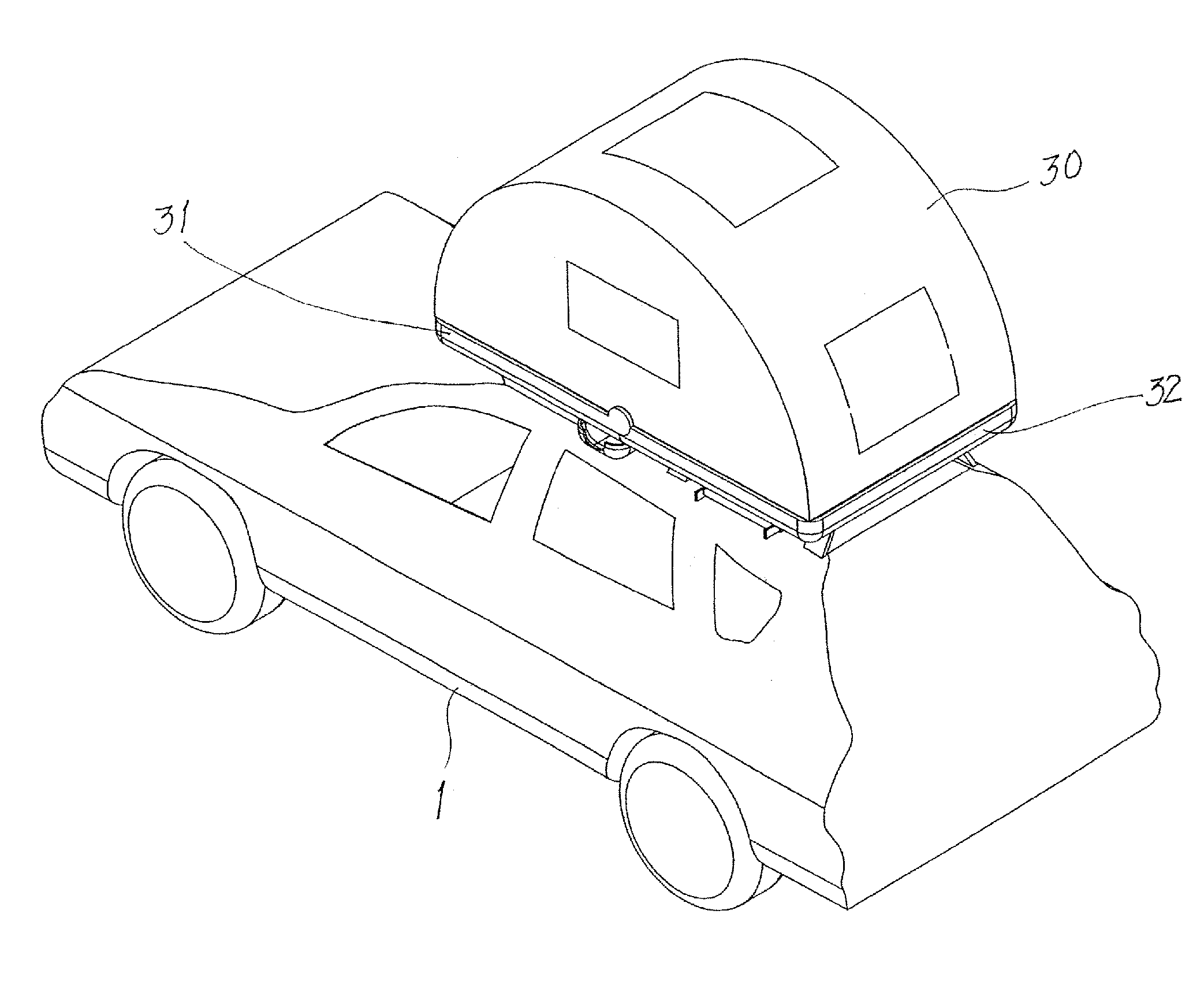
[0006]The present invention aims to provide a car-top tent that comprises a top cover and a bottom base. The bottom base is mounted to a rear portion of the roof of a car. The top cover forms an opening, which, when the tent is opened, is put in alignment with a sunroof of the car. An expandable canopy is arranged between the top cover and the bottom base. When the top cover is opened, the canopy is pulled and expanded. With the alignment of the opening of the top cover with the sunroof, the tent can be accessed through the sunroof. This enhances the safety and eliminates the potential risk of undesired accident. The top cover and the bottom base, when opened, form an accommodation space therebetween in which a sleep mat composed of multiple pieces is received. The sleep mat is formed so as to be adjustable in the angular position thereof, which besides serving as a bed for a user to lie down thereon can function as a deck chair allowing a user to sit or lie thereon for watching sunrise and sunset or enjoy sight seeing of the surrounding landscape to realize the purposes of vocation, entertainment, or exercise.

Problems solved by technology

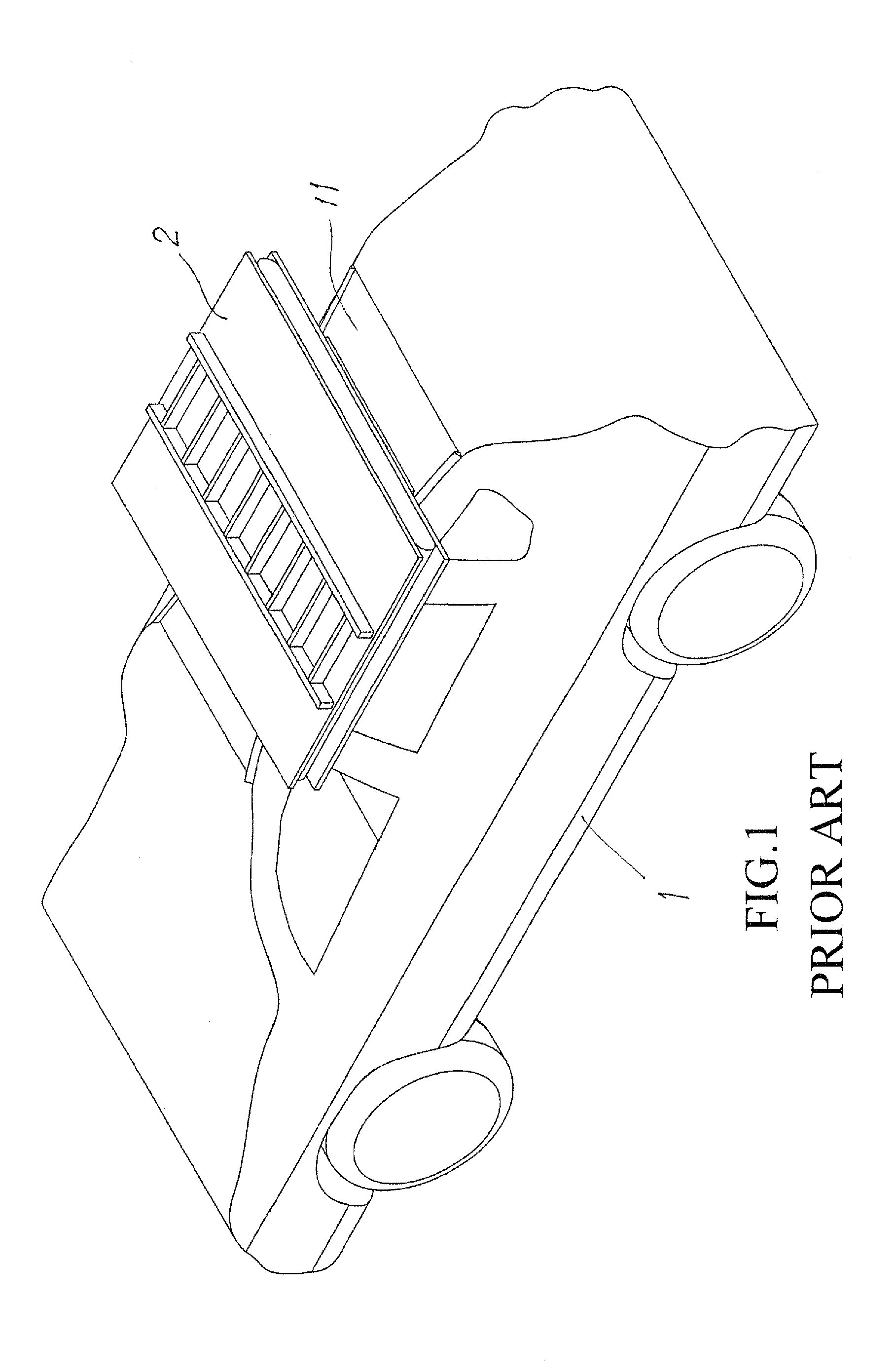
(1) When the tent is put on the car top and not in use, the tent does not match the appearance of the car, making the car look ugly and further, when the car is traveling, the tent causes a great wind resistance and is susceptible to vibration, so that it increases the consumption of fuel.
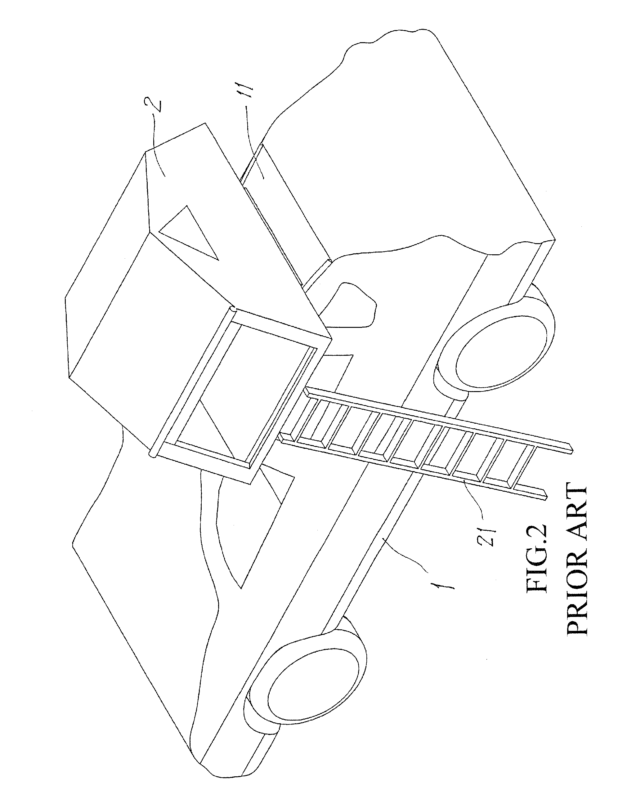
(2) Using the ladder 21 to move in and out of the tent 2 may cause undesired safety problems for a user may get fallen off the ladder.
(3) Using the ladder 21 to move in and out of the tent 2 allows any unauthorized person to access the tent and this is extremely dangerous in a wild area.

Method used


Image

  • Car-top tent
  • Car-top tent
  • Car-top tent

Examples


Embodiment Construction

[0020]The following descriptions are exemplary embodiments only, and are not intended to limit the scope, applicability or configuration of the invention in any way. Rather, the following description provides a convenient illustration for implementing exemplary embodiments of the invention. Various changes to the described embodiments may be made in the function and arrangement of the elements described without departing from the scope of the invention as set forth in the appended claims.

[0021]Referring to FIG. 3, which is a perspective view showing a car-top tent according to the present invention mounted to the top of a car, the car, which is generally designate at 1, comprises a roof 11 in which a sunroof 10 is mounted. The car-top tent of the present invention, generally designated at 3, comprises a bottom base 32 that is mounted and fixed to the car roof 11 and a top cover 31 that, when not in use, is folded to overlap atop the bottom base 32. When the tent is put into use, a u...


PUM


Abstract

A car-top tent includes a top cover and a bottom base and is mounted to the top of a car. The tent can be folded on a rear portion of the car roof. The top cover forms an opening, which, when the tent is opened, is put in alignment with a sunroof of the car. When the top cover is opened, the tent is driven to expand so that when the top cover is moved to an angular position to be substantially flush with the bottom base, the tent is completely expanded on the car top. A sleep mat composed of multiple pieces is received in recesses defined in the top cover and the bottom base and is adjustable in angular position thereof. The tent can be accessed directly from inside the car through the sunroof so as to offer enhanced safety and be suitable for entertainment, vocation, and exercise.

Description

TECHNICAL FIELD OF THE INVENTION[0001]The present invention generally relates to a structure of car-top tent, and more particularly to a car-top tent comprising a top cover that forms an opening, which when the top cover is opened, is put in alignment with a sunroof of the car to allow access to the tent through the sunroof, so as to realize folding of the tent on the car roof.DESCRIPTION OF THE PRIOR ART[0002]A car-top tent is a common and popular recreational product. As shown in FIG. 1 of the attached drawings, a foldable tent 2 is mounted to the roof 11 of a car 1 with bottom of the tent fixed to the car roof 11. The use of the tent is shown in FIG. 2, where a ladder 21 that is provided on a side of the tent 2 is pulled off to expand the tent 2 and the ladder 21 is then positioned on ground to allow a user to enter and leave the tent through the ladder 21. Although it works, it still shows drawbacks:[0003](1) When the tent is put on the car top and not in use, the tent does not ...

Claims


Application Information

Patent Timeline
Patent Type & Authority Applications(United States)
IPC IPC(8): E04H15/06
CPCE04H15/06A61P35/00
Inventor CHIU, CHAO HSIUNG
Owner CHIU CHAO HSIUNG
Learn More