
Virtual Code Window

Inactive Publication Date: 2010-10-21
FILTRONA C
View PDF8 Cites 5 Cited by
  • Summary
  • Abstract
  • Description
  • Claims
  • Application Information

AI Technical Summary

Problems solved by technology

The data may be used or manipulated for unauthorised purposes; which greatly reduces the effectiveness of such codes as security or track and trace devices.
It is particularly difficult to copy this code for a number a reasons.
Firstly, it is difficult to reproduce the code with the degree of accuracy required, i.e. such that a reading machine would fail to distinguish between the line position of an original code and that of a copy and would generate the same alphanumeric descriptor as would have been generated when scanning the original code.
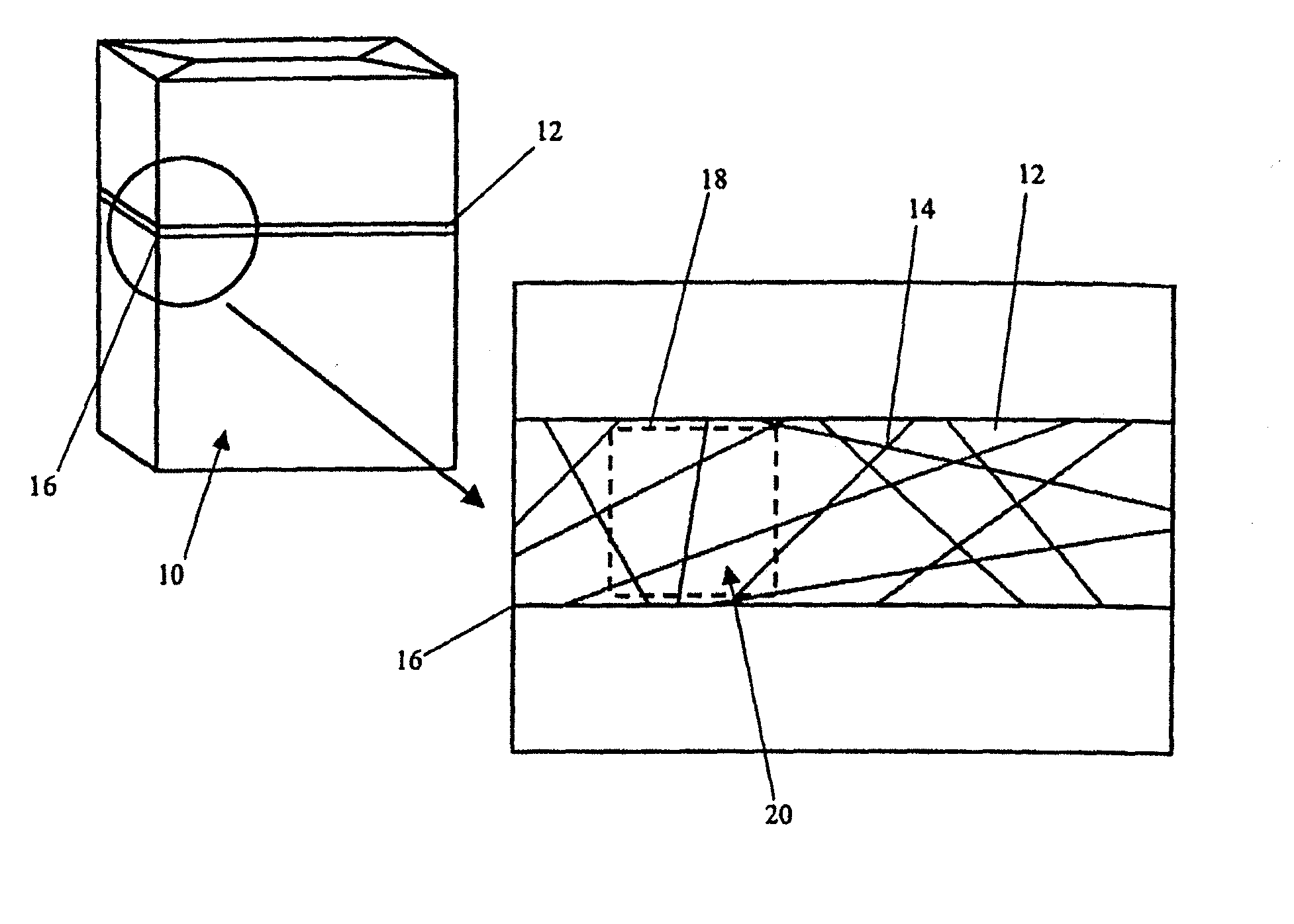
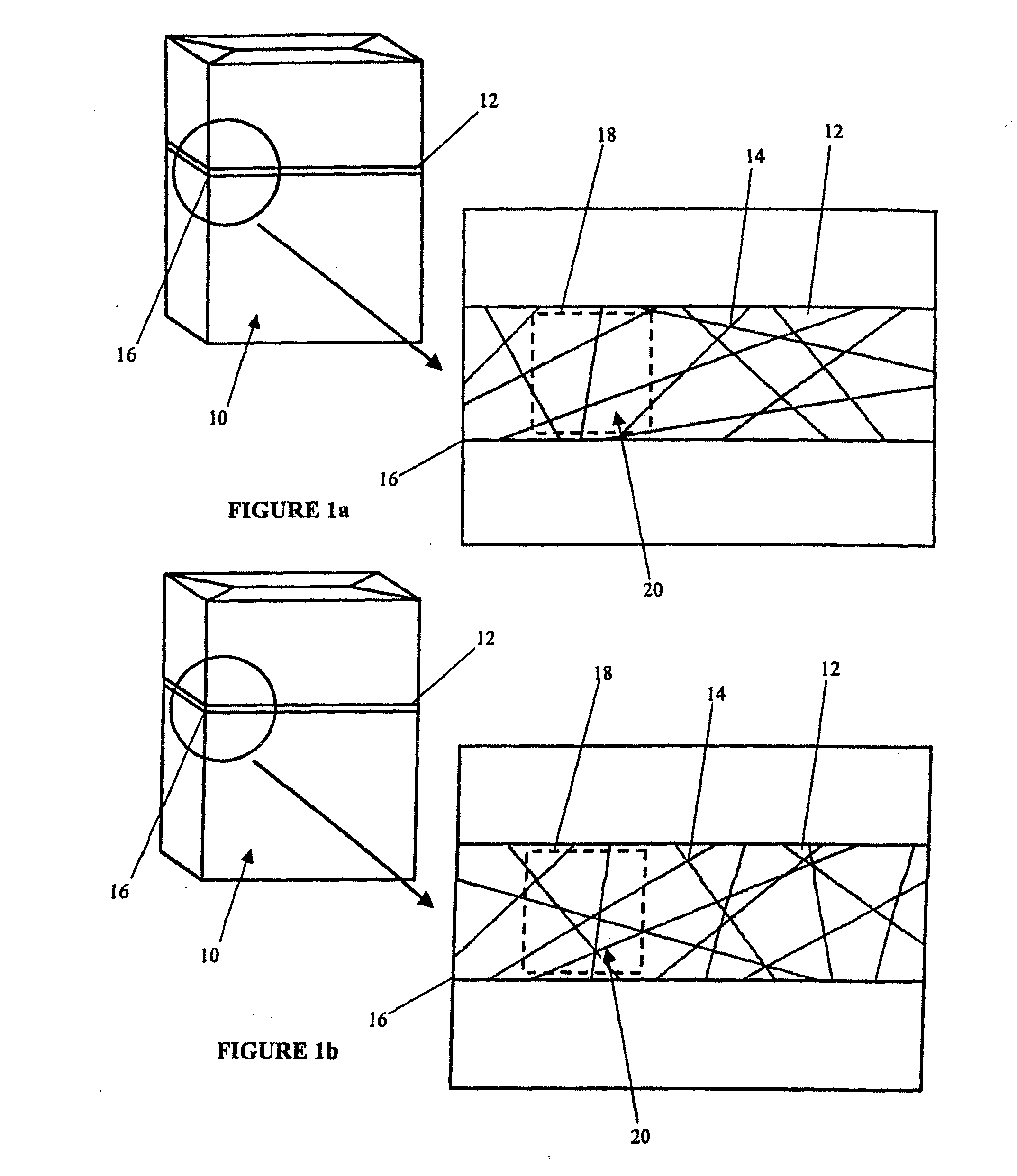
Further, even if the algorithm were to be known, the data corresponding to the alphanumeric descriptor cannot be obtained without access to a secure database.Although these codes are difficult to copy and guess, since only the area delimited by the rectangular box, or some other graphical boundary, is of any interest, the only portion that needs to be reproduced by any unauthorised user is the code window and the area within it.
This means that the whole of the graphical pattern on the substrate need not be copied and any line pattern not within the code window is effectively redundant.
There are several disadvantages associated with such a system.
Therefore its uniqueness cannot be guaranteed and unwanted replication cannot be mathematically ruled out.
Thirdly, if a plurality of identifying areas are desired, for example, for reasons of added security, this can only be achieved by having a plurality of reference points to define the respective identifying areas.
This may interfere with the aesthetics of the object, or more importantly, reveal the significance of the reference points to a potential counterfeiter.

Method used


Image

  • Virtual Code Window
  • Virtual Code Window
  • Virtual Code Window

Examples


second embodiment

[0043]FIG. 4 schematically shows the invention. An article 30, in the form of an identification card, has a plurality of straight lines 34 printed over its surface 32 which are arranged at different angles such that at least some of the lines intersect each other. The pattern of coding lines 34 over the surface 32 is fixed for each of a plurality of articles 30 and therefore every article in a series has the same pattern of lines on its surface. Additionally, on the surface 32 of the card 30 is printed a trigger point 36 which in this example is a non-symmetrical mark and a machine readable code 44. The machine readable code may be an alphanumeric code or a barcode, for example. If the machine readable code is a barcode it could be almost any of the currently known codes referred to collectively as “barcodes” and including, but not limited to, such codes as: Data Matrix, PDF-417, Micro-PDF-417, QR Code, MaxiCode, Codabar, RSS, and linear barcodes.

[0044]The coding lines 34, trigger p...

first embodiment

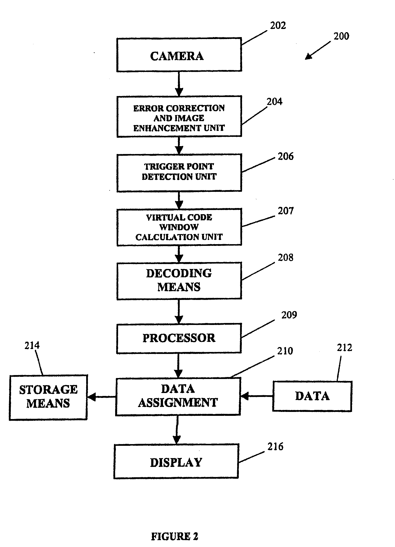
[0046]Referring to FIG. 5, an apparatus 200 for reading the coding lines 34 and assigning data thereto is schematically shown. This is substantially the same as the apparatus shown in FIG. 2 except there is a barcode decoder 205. The method for assigning data to the code 40 is the same as for the first embodiment except the coordinates of the virtual code window 38 are determined by decoding the barcode 44 on the article as opposed to the co-ordinates being pre-defined in the machine.

[0047]FIG. 6 schematically shows a hand-held reading apparatus 300 for reading the code 40 on an article 30. This is substantially the same as the apparatus shown in FIG. 3 except there is a barcode decoder 305. The method for reading the code 40 is substantially the same as for the first embodiment except scanning the barcode 44 and decoding it determines the co-ordinates of the virtual code window 38 relative to the trigger point 36.

[0048]FIG. 7 illustrates a third embodiment of the invention. This is...


PUM


Abstract

A machine readable code is defined by a portion of graphical indicium located on a substrate; wherein the code is delimited by a temporary boundary that is generated by a reading machine relative to a fixed trigger point only when the code is being read.

Description

CROSS REFERENCE TO RELATED APPLICATION[0001]This is a continuation application of Ser. No. 12 / 024,735 filed Feb. 1, 2008 entitled “Virtual Code Window” which is a National filing of a corresponding co-pending application filed in the United Kingdom as U.K. Serial No. GB0702090.2, filed Feb. 2, 2007, entitled “Virtual Code Window” for which priority is claimed and which are incorporated herein by reference.BACKGROUND OF THE INVENTION[0002]The present invention relates to graphic codes and in particular graphic codes that are defined by a code window.[0003]Codes that are graphically represented and machine-readable are well-known. Such codes are commonly used on consumer and commercial products and when read may provide information relating to the cost, line item, or origin of the product, for example. These types of codes may be used for automating check-outs at supermarkets, for stock control purposes or for verifying the correct product is in the correct packaging. More complex mac...

Claims


Application Information

Patent Timeline
IPC IPC(8): G06F17/00G06Q90/00G06K19/06G06V30/224
CPCG06K7/14G06K19/086G06K19/06037G06K19/06046G06T7/00G06V10/22
Inventor PINCHEN, STEPHEN PAULRASMUSSEN, JENS JACOB JUUL
Owner FILTRONA C
Learn More