Surface mount thin film fuse structure and method of manufacturing the same

a thin film fuse and surface mount technology, applied in the direction of basic electric elements, emergency protective devices, electric devices, etc., can solve the problems of easy damage or burn of electronic circuits of electric devices, increasing the density of circuits and components on printed circuit boards, and affecting the safety of users

Inactive Publication Date: 2010-10-21
YEN CHUN CHANG
View PDF37 Cites 15 Cited by
  • Summary
  • Abstract
  • Description
  • Claims
  • Application Information

AI Technical Summary

Benefits of technology

[0008]The primary objective of the present invention is to provide a surface mount thin film fuse structure and a method of manufacturing the surface mount thin film fuse structure that assure the effect of blowing the fuse at a specific current or a specific temperature to protect a circuit against an overload current.
[0009]To achieve the foregoing objective, the present invention provides a surface mount thin film fuse structure comprising a fusible fuse circuit structure disposed on at least one side of an insulating substrate, and having a fusible link portion electrically connected between two opposite electrode portions, such that when an overload current is passed through fusible link portion, a heat source of a high temperature or a specific temperature is generated to blow the fuse to achieve the an over current protection effect, and at least one space is defined between the fusible link portion and the insulating substrate, such that a heat generated by the electrically energized the fusible link portion will not be dissipated through the heat conduction of the insulating substrate, so as to assure the effect of blowing the fuse at a specific current or a specific temperature to protect a circuit.

Problems solved by technology

In general, an electric device is set to consume a maximum current for its use, and thus the device may be damaged or burned by an overload current easily, and a fuse is provided to prevent an overload current from passing through an electronic circuit.
Since the electric devices become more complicated and require more components, the layout of circuits and components on the printed circuit board becomes increasingly denser.
As a result, the electronic circuits of the electric devices will be damaged or burned easily.

Method used


Image

  • Surface mount thin film fuse structure and method of manufacturing the same
  • Surface mount thin film fuse structure and method of manufacturing the same
  • Surface mount thin film fuse structure and method of manufacturing the same

Examples


Embodiment Construction

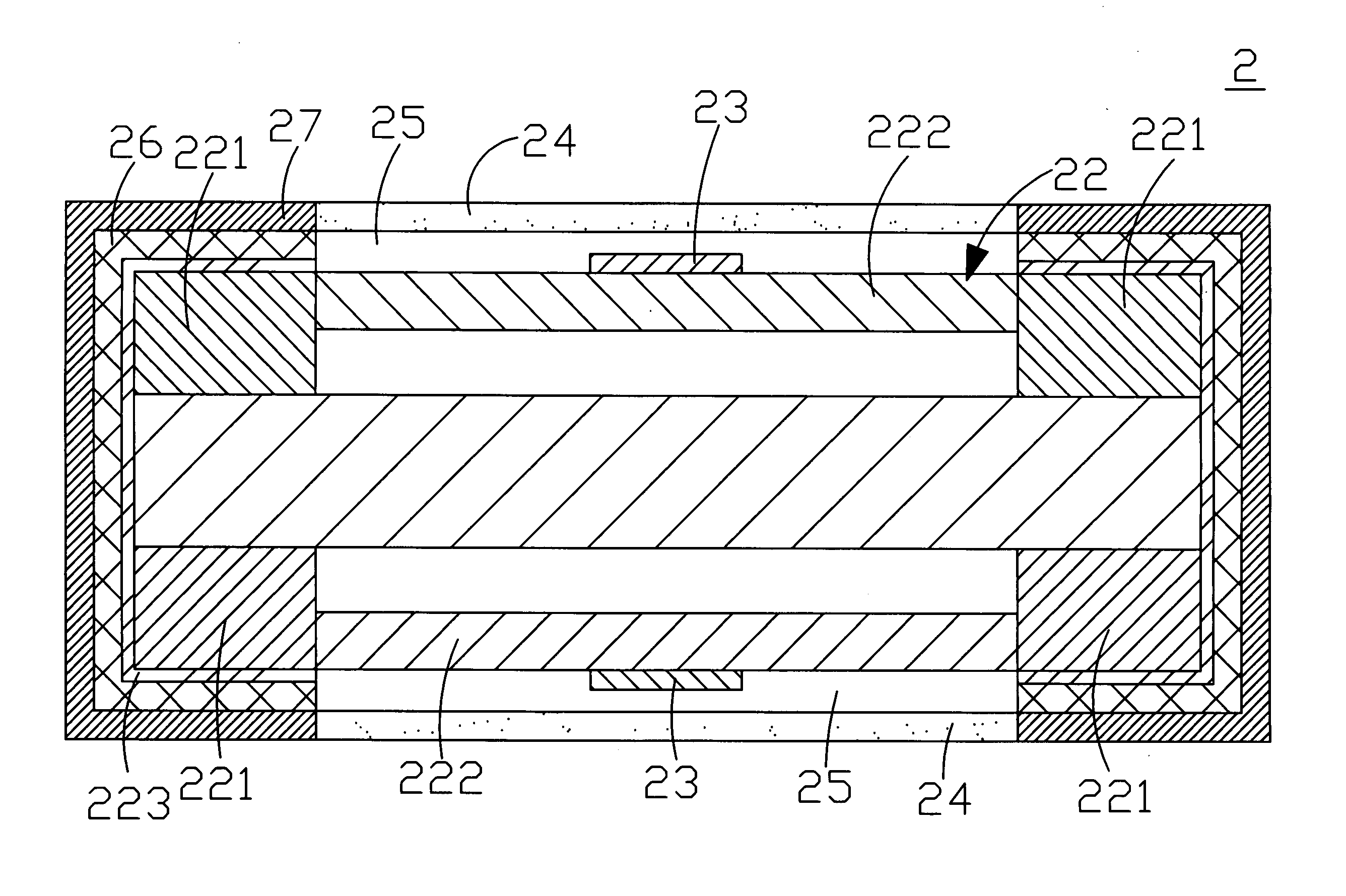
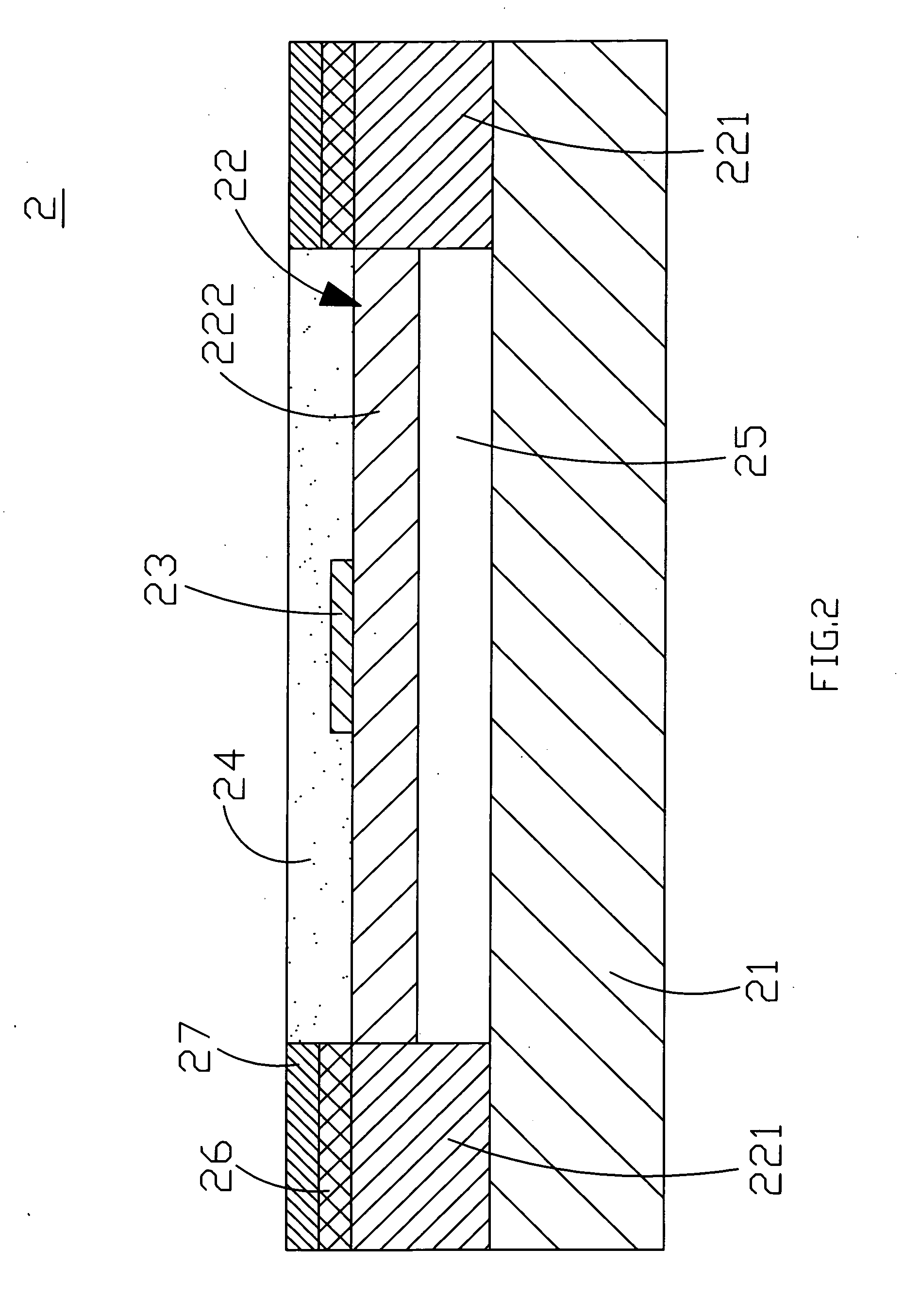
[0020]Referring to FIGS. 2 and 3 for a surface mount thin film fuse structure and a method of manufacturing the surface mount thin film fuse structure in accordance with the present invention, the surface mount thin film fuse structure 2 comprises a fusible fuse circuit structure 22 disposed on at least one surface of an insulating substrate 21, and further comprising two opposite electrode portions 221 and a fusible link portion 222, wherein the fusible link portion 222 is connected electrically to the two opposite electrode portions 221, and the fusible link portion 222 has a tin layer 23 disposed at the middle of a surface of the fusible link portion 222, and a protective layer 24 disposed on the fusible link portion 222 of the fusible fuse circuit structure for preventing the fusible link portion 222 and the tin layer 23 from being oxidized or sputtered by melted metals. At least one space 25 is defined between the fusible link portion 222 and the insulating substrate 21, such t...


PUM

PropertyMeasurementUnit
melting pointaaaaaaaaaa
pressureaaaaaaaaaa
temperatureaaaaaaaaaa

Abstract

The present invention discloses a surface mount thin film fuse structure including a fusible fuse circuit structure disposed on a side of an insulating substrate, and the fusible fuse circuit structure has a fusible link portion electrically connected between two opposite electrode portions. If an overload current is passed through the fusible link portion, the fusible link portion will be melted down by a high temperature or a specific temperature to achieve the over current protection effect. At least one space is defined between the fusible link portion and the insulating substrate, such that a heat generated by the electrically energized the fusible link portion will not be dissipated through the heat conduction of the insulating substrate to achieve the circuit protection effect.

Description

BACKGROUND OF THE INVENTION[0001](a) Field of the Invention[0002]The present invention relates to a surface mount thin film fuse structure and a method of manufacturing the surface mount thin film fuse, and more particularly to a surface mount thin film fuse and a method of manufacturing the surface mount thin film fuse that assure the effect of blowing the fuse at a specific current or a specific temperature to protect a circuit against an overload current.[0003](b) Description of the Prior Art[0004]In general, an electric device is set to consume a maximum current for its use, and thus the device may be damaged or burned by an overload current easily, and a fuse is provided to prevent an overload current from passing through an electronic circuit. If an overload current is passed through a fuse, the fuse will produce a high temperature to blow the fuse in order to protect the circuit from being damaged. In present existing electric devices such as information, communication and co...

Claims


Application Information

Patent Timeline
Patent Type & Authority Applications(United States)
IPC IPC(8): H01H85/02H01H69/02
CPCH01H69/022H01H85/0047Y10T29/49107H01H2085/0414H01H85/0411
Inventor YEN, CHUN-CHANG
Owner YEN CHUN CHANG
Why Eureka
Try Eureka