Retro-reflector

a retro-reflector and article technology, applied in the direction of instruments, roads, traffic signals, etc., can solve the problems of reducing the apparent area of the exposure surface, the inferior retro-reflection range of the conventional retro-reflective article at high angles of incidence, etc., and achieve the effect of widening the retro-reflection range and increasing the retro-reflective ratio

Inactive Publication Date: 2010-10-21
KIM HYEONSIK +1
View PDF5 Cites 24 Cited by
  • Summary
  • Abstract
  • Description
  • Claims
  • Application Information

AI Technical Summary

Benefits of technology

[0019]The retroreflective article according to the present invention can increase its retroreflective ratio by reflecting an incident light using three or more than three reflecting surfaces according to it

Problems solved by technology

However, the conventional retroreflective article has an inferior retro-reflection range at high angles of incidence because for the light having high incident angle the retroreflective article has low retroreflective ratio which is expressed as the ratio of the quantity of incident light to the quantity of retro-reflected light is low.
However, when the incident angle of the light becomes large due to movement of the light source, the apparent area of the exposure surface (i.e. the area of the exposure surface when viewed from the direction of the light source) has no alternative but to be geometrically reduced.
At this time, because the percentage of the retro-reflection area capable of retro-reflecting the light incident on the exposure surface is further reduced, the conventional retroreflective article using cube corners has a problem in that the brightness is sharply lowered in proportion to the magnitude of the incident angle.
Therefore, the retro-reflection range of the incident angle, i.e. the visible retro-reflectio

Method used


Image

  • Retro-reflector
  • Retro-reflector
  • Retro-reflector

Examples


first embodiment

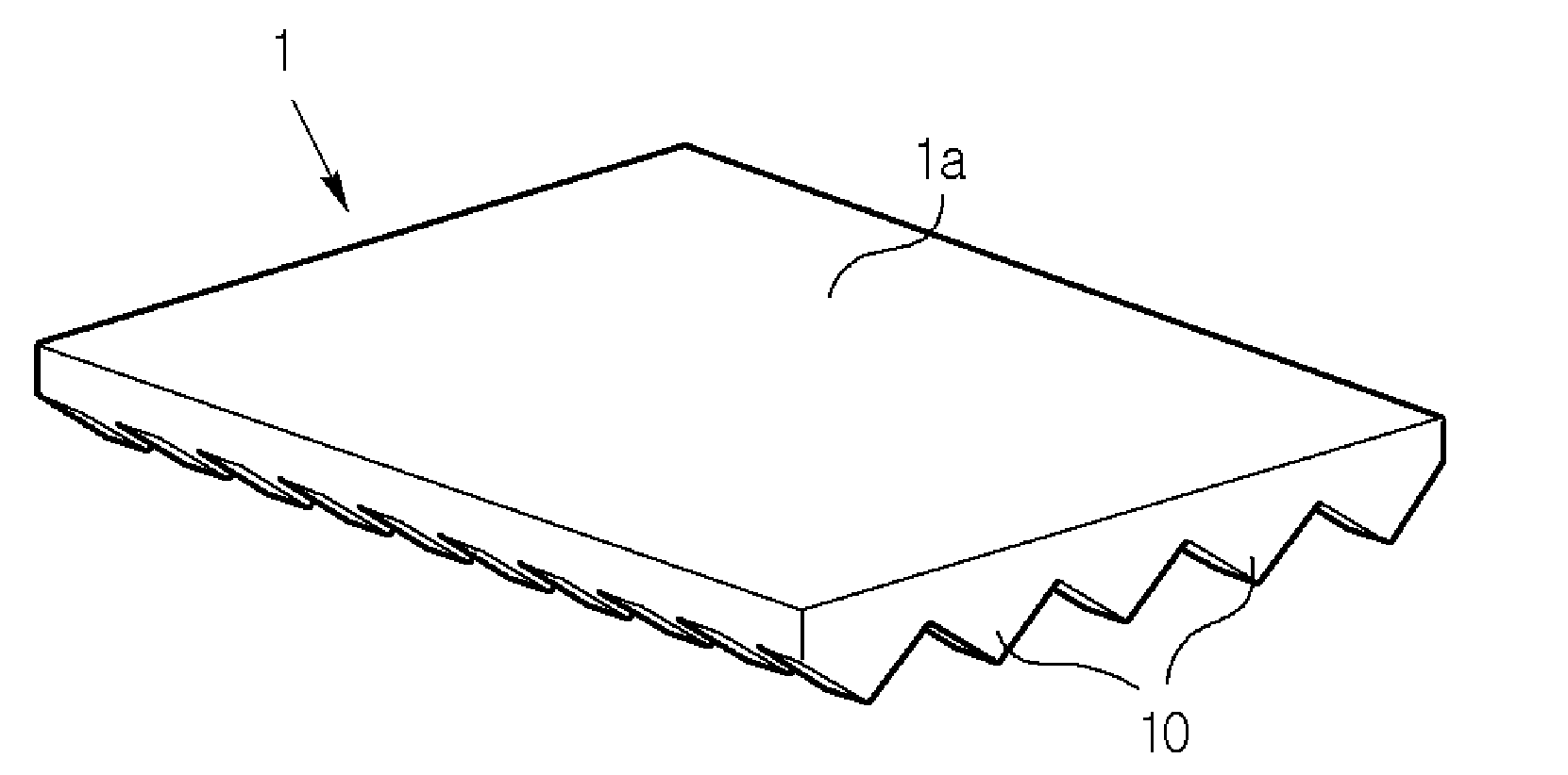
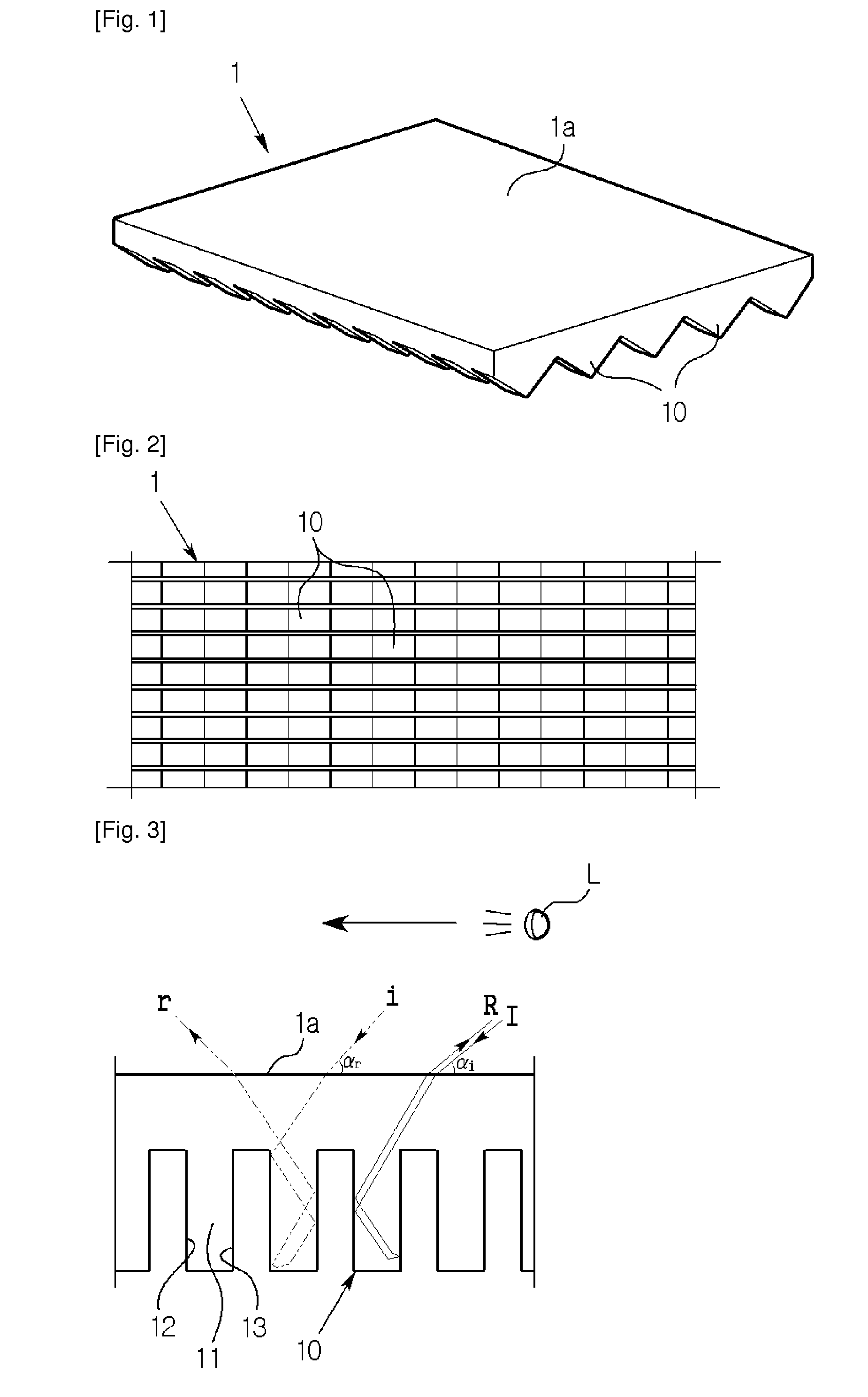
[0050]FIG. 1 shows a partially enlarged perspective view illustrating a retroreflective article according to a first embodiment of the present invention. FIGS. 2 and 3 show plane and side views of the retroreflective article in FIG. 1.

[0051]As shown, the retroreflective article 1 according to this first embodiment is formed with a flat light receiving surface 1a on the upper portion thereof and formed with retroreflective elements 10 to be closely arranged with a constant pattern on the bottom surface thereof.

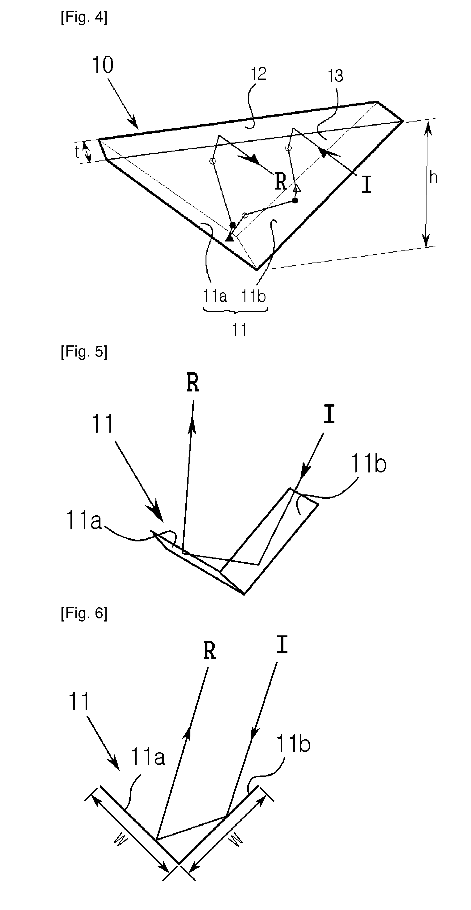
[0052]FIG. 4 is an enlarged perspective view of the retroreflective elements 10 which retroreflect the incident light which is entered through the receiving surface 1a in the retroreflective article 1.

[0053]As shown, the retroreflective element 10 of this first embodiment is composed of a reflecting corner 11 having light and right corner reflecting surfaces 11a and 11b which are perpendicular from each other, and a pair of vertical reflecting surfaces 12 and 13 vertically form...

second embodiment

[0064]FIGS. 12 and 13 are side views illustrating a retroreflective path of the retroreflective article according to a second embodiment of the present invention, and FIG. 14 is a partially enlarged perspective view illustrating a retroreflective element according to a second embodiment of the present invention.

[0065]As shown, the retroreflective element 20 of the retroreflective article according to this second embodiment includes a reflecting corner row 21 composed of reflecting corners 210 arranged in parallel on the same plane and becoming a bottom portion of the retroreflective element 20, and a pair of vertical reflecting surfaces 22 and 23 formed on both sides of the reflecting corner row 21 to be perpendicular with the reflecting corner 10 with a distance (t) smaller than its vertical height (h).

[0066]As shown in FIG. 15, the reflecting corners 210 forming the reflecting corner row 21 on the bottom portion of the retroreflective element 20 has a reflecting structure in which...

third embodiment

[0074]FIG. 24 shows a partially enlarged perspective view of a retroreflective article according to a third embodiment of the present invention, and FIG. 27 shows a side view of the retroreflective article in FIG. 24. And, FIG. 26 shows a partially enlarged perspective view of a retroreflective element of the retroreflective article according to the third embodiment.

[0075]The retroreflective article 3 according to the third embodiment of the present invention is manufactured to have thin plate shape with light permeable materials such as glasses, crystal, PMMA (Poly Methyl Meta Acrylate), polycarbonate, ultraviolet cured resin, acrylic. The article 3 can be covered with various cover layers such as a layer for covering the retroreflective article, an adhesive layer to be adhered on other objects, or a reflecting layer made of lustrous materials to increase the retroreflective ratio, on a receiving surface 3a of the bottom surface of upper portion thereof.

[0076]As shown in FIGS. 24 a...


PUM


Abstract

The present invention relates to a retroreflective article enabling to retroreflect incident light in its incident direction, and the retroreflective article including at least one retroreflective element, the retroreflective element comprising at least one reflecting corner comprised of a pair of corner reflecting surfaces which meet at dihedral angle of about 90 degree; and a pair of vertical reflecting surfaces which are formed on both ends of the reflecting corner to be substantially perpendicular to a corner of the reflecting corner with a distance which is smaller than the highest vertical height and which meet at dihedral angle of about 90 degree for the pair of corner reflecting surfaces. This retroreflective article has higher retroreflective ratio and wider available retroreflective range, and it is designed to be freely changed its main reflecting direction having the highest retroreflective ratio.

Description

TECHNICAL FIELD[0001]The present invention relates to a retroreflective article, and more particularly, to a retroreflective article enabling to retroreflect incident light in its incident direction.BACKGROUND ART[0002]A variety of traffic safety facilities such as traffic signs, pavement markers, delineators and tripods or goods which should be importantly confirmed their visibility at rainy day or at night such as safety clothes, automobiles, bicycles, helmets and shoes are installed with or attached with a retroreflective article enabling to increase the visibility for the goods by retro-reflecting the incident light from front side thereof toward the light source radiating the light.[0003]Conventionally, a retroreflective article provided with a glass bead or a cube corner has been usually used as the retroreflective article which will be applied to the goods which should be importantly confirmed their visibility.[0004]However, the conventional retroreflective article has an inf...

Claims


Application Information

Patent Timeline
IPC IPC(8): G02B5/124E01F9/619
CPCG02B5/124B60Q7/005G02B5/122
Inventor KIM, HYEONSIKKIM, BONGJU
Owner KIM HYEONSIK
Why Eureka
Try Eureka