Ultrasound emitting device comprising a head frame

a technology head frame, which is applied in the field of ultrasonic emitting device comprising a head frame, can solve the problems of life-threatening, formation and development of blood clots

Inactive Publication Date: 2007-07-19
CEREVAST THERAPEUTICS
View PDF7 Cites 21 Cited by
  • Summary
  • Abstract
  • Description
  • Claims
  • Application Information

AI Technical Summary

Benefits of technology

[0033]FIG. 13A shows the effective acoustic fields produced using Applicants' ultrasound emitting device comprising a sound head matrix comprising two planar arrays of transducers attached to one another to define an interior dihedral angle less than 180 degrees;
[0034]FIG. 13B shows the effective acoustic fields produced using the apparatus of FIG. 11B comprising two ultrasound emitting devices, wherein each device comprises a sound head matrix comprising two planar arrays of transducers attached to one another to define an interior dihedral angle less than 180 degrees;
[0035]FIG. 14A shows the effective acoustic fields produced using Applicants' ultrasound emitting device comprising a sound head matrix formed using four offset planar arrays of transducers;
[0036]FIG. 14B shows the effective acoustic fields produced using two ultrasound emitting devices, wherein each of those devices comprises a sound head matrix formed using four offset planar arrays of transducers.

Problems solved by technology

Thrombosis, the formation and development of a blood clot or thrombus within the vascular system, can be life threatening.

Method used


Image

  • Ultrasound emitting device comprising a head frame
  • Ultrasound emitting device comprising a head frame
  • Ultrasound emitting device comprising a head frame

Examples


example i

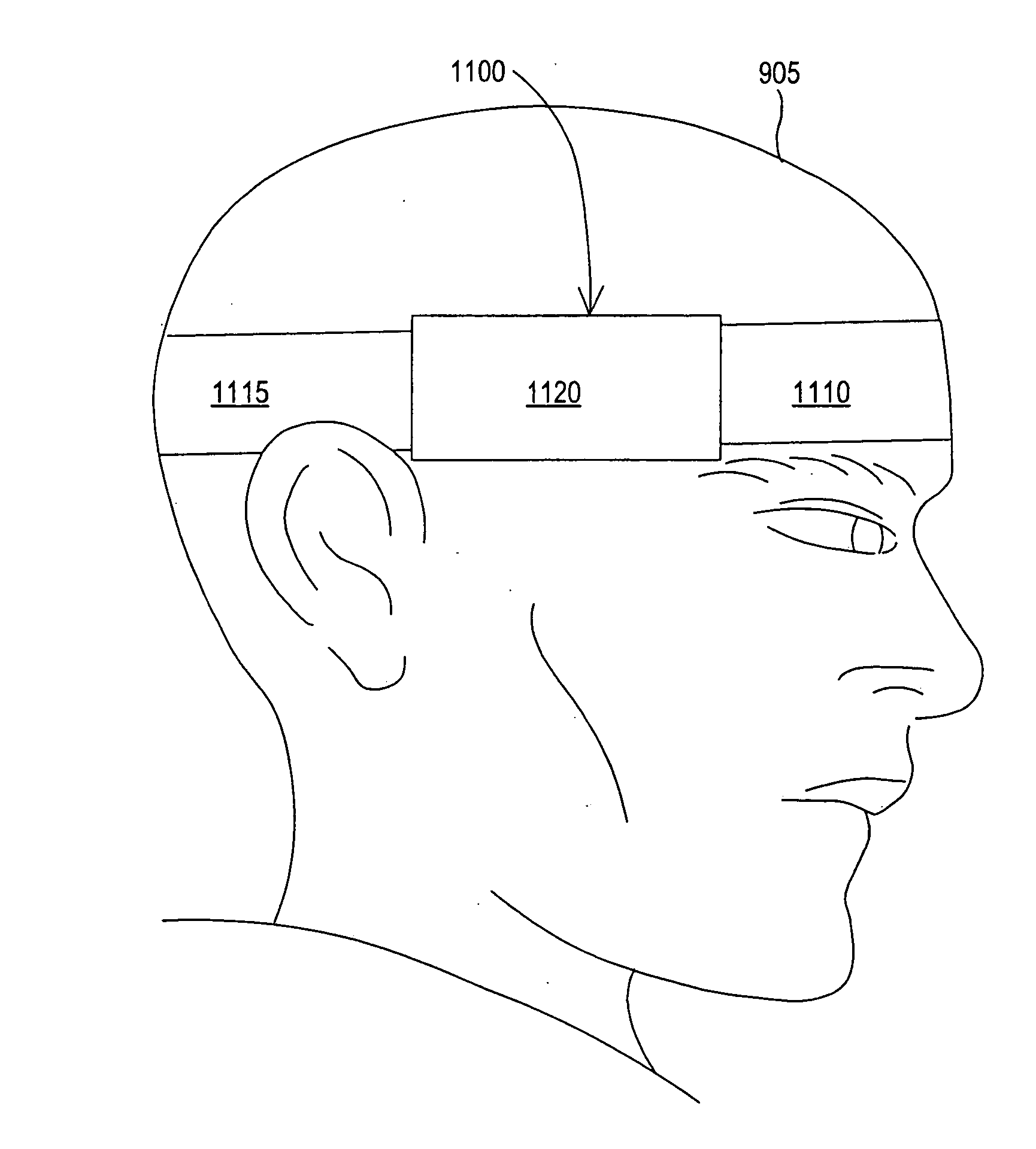
[0155] Referring now to FIGS. 2A, 4A, 4B, 4C, 11A, 11B, and 13A, this Example I uses ultrasound emitting apparatus 200 (FIG. 4A, 4B) or ultrasound emitting apparatus 201 (FIG. 4C), externally disposed over a patient's temporal window as shown in FIGS. 11A and 11B, wherein apparatus 200 / 201 comprises sound head matrix 401 (FIG. 4A), wherein the interior dihedral angle, as defined hereinabove, is between 155 and 175 degrees.

[0156]FIG. 13A shows the effective acoustic fields 1310 and 1320 produced by Applicants' ultrasound emitting apparatus 200 / 201. The overlapping fields are shown by shading.

[0157] In certain embodiments, the frequency and / or the phase of the acoustic waves emitted by ultrasound transducers 441, 442, 443, 444, 445, 446, 447, 448, 451, 452, 453, 454, 455, 456, 457, and 458, are modulated such that, at any given time, none of those transducer are emitting acoustic waves having the same frequency and phase. In certain embodiments, transducers 441, 442, 443, 444, 445, ...

example ii

[0159] Referring now to FIGS. 2A, 4A, 4B, 4C, 12, and 13B, this Example II uses a first ultrasound emitting apparatus 200 (FIG. 4B) or 201(FIG. 4C) and a second ultrasound emitting apparatus 200B or 201B, wherein first apparatus 200A / 201A and second apparatus 200B / 201B are externally disposed bilaterally over a patient's temporal windows as shown in FIG. 12, wherein apparatus 200A or 201A and apparatus 200B or 201B each comprise sound head matrix 401 (FIG. 4A), wherein the interior dihedral angle for both apparatus 200A / 201B and 100B, is between about 155 degrees and about 175 degrees.

[0160]FIG. 13B shows the effective acoustic fields 1310 and 1320 produced by Applicants' ultrasound emitting apparatus 200A or 201A, in combination with acoustic fields 1330 and 1340 produced by Applicants' ultrasound emitting apparatus 200B or 201B. The overlapping fields are shown by shading.

[0161] In certain embodiments, the frequency and / or the phase of the acoustic waves emitted by ultrasound tr...

example iii

[0162] Referring now to FIGS. 3A, 5A, 11A, 11B, and 14A, this Example III uses ultrasound emitting apparatus 300 (FIG. 5B) or ultrasound emitting apparatus 301 (FIG. 5C), externally disposed over a patient's temporal window as shown in FIGS. 11A and 11B, wherein apparatus 300 / 301 comprises sound head matrix 501 (FIG. 5A), wherein interior dihedral angles 518, 528, and 538 are between about 155 degrees and about 175 degrees.

[0163]FIG. 14A shows the effective acoustic fields 1410, 1420, 1430, and 1440, produced by subassemblies 550 (FIG. 5A), 560 (FIG. 5A), 570 (FIG. 5A), and 580 (FIG. 5A). In certain embodiments, the frequency and / or the phase of the acoustic waves emitted by ultrasound transducers 514, 515, 516, 517, 524, 525, 526, 527, 534, 535, 536, 537, 544, 545, 546, and 547, are modulated such that, at any given time, none of those transducer are emitting acoustic waves having the same frequency and phase. In certain embodiments, transducers 514, 515, 516, 517, 534, 535, 536, ...


PUM


Abstract

An ultrasound emitting device is disclosed. The ultrasound emitting device includes a sound head matrix comprising a first planar member, and a second planar member, wherein the first planar member is attached to the second planar member to form a V-shaped assembly comprising a first interior dihedral angle, where that first interior dihedral angle is between about 155 degrees and about 175 degrees. The ultrasound emitting device further comprises a first plurality of ultrasound transducers disposed on the first planar member, and a second plurality of ultrasound transducers disposed on the second planar member.

Description

CROSS REFERENCE TO RELATED APPLICATIONS [0001] This Application claims priority from a U.S. Provisional Application having Ser. No. 60 / 737,980 filed Nov. 18, 2005, and from a U.S. Provisional Application having Ser. No. 60 / 738,080 filed Nov. 18, 2005.FIELD OF THE INVENTION [0002] Applicants' invention relates to an ultrasound emitting device comprising a head frame, and a method using that device. BACKGROUND OF THE INVENTION [0003] Thrombosis, the formation and development of a blood clot or thrombus within the vascular system, can be life threatening. The thrombus can block a vessel and stop blood supply to an organ or other body part. If detached, the thrombus can become an embolus and occlude a vessel distant from the original site. [0004] Dissolution of thrombus using ultrasound is known in the art. Further, the ability of microbubbles to potentiate ultrasound-induced thrombolysis is known. The bubbles are destroyed by the ultrasound and the energy is released into the clot. [00...

Claims


Application Information

Patent Timeline
Patent Type & Authority Applications(United States)
IPC IPC(8): A61B8/00
CPCA61B5/6814A61B8/0816A61B8/0833A61B8/14A61B8/4227A61B8/4281A61N2007/0078A61B8/4483A61B8/481A61B8/546A61B2019/262A61N7/02A61B8/4472A61B5/4076A61B2090/502
Inventor UNGER, EVAN C.ALEXANDROV, ANDREI
Owner CEREVAST THERAPEUTICS
Why Eureka
Try Eureka