
Fixed-focus lens

a fixed-focus lens and lens body technology, applied in the field of lenses, can solve the problems of higher manufacturing difficulty, higher cost and production difficulty of aspheric lenses, and difficult assembly of lenses, so as to reduce the cost of optical components, reduce the cost of lenses and the volume of fixed-focus lenses, and good imaging quality

Inactive Publication Date: 2010-10-21
YOUNG OPTICS
View PDF10 Cites 15 Cited by
  • Summary
  • Abstract
  • Description
  • Claims
  • Application Information

AI Technical Summary

Benefits of technology

[0008]Accordingly, the invention is directed to a fixed-focus lens, which is able to provide good imaging quality, and meanwhile reduce the cost of the optical components, the fabrication difficulty of the lenses and the volume of the fixed-focus lens.
[0011]In the fixed-focus lens of the embodiment of the invention, the distortion, the astigmatism and the field curvature of imaging may be reduced through a combinational disposition of the aspheric lens and the spherical lens in the first lens group. Meanwhile, the spherical aberration and the coma may be reduced by alternately arranging at least a part of the spherical lenses in the second lens group so as to make the positive refractive powers and the negative refractive powers thereof alternately arranged. In this way, the fixed-focus lens of the embodiment of the invention is able to produce good imaging quality. Further, since the fixed-focus lens of the embodiment of the invention employs a less number of aspheric lenses (for example, usually a piece only), the fixed-focus lens is advantageous in having good imaging quality, saving the cost of the optical components and reducing the fabrication difficulty of the lenses. Moreover, the fixed-focus lens of the embodiment of the invention employs less number of the lenses, such that the volume of the fixed-focus lens is reduced. In addition, since the fixed-focus lens is designed under the condition of F / H>0.627, so that a wider FOV is achieved without degrading the imaging quality.

Problems solved by technology

However, the cost and the production difficulty of the aspheric lens are higher.
The aspheric lens also makes the assembly of the lens more difficult.
The more the employed aspheric lenses, the higher the fabrication difficulty and the cost are.
A larger total length of the wide-angle lens results in a larger volume of the projection apparatus and an expensive cost.

Method used


Image

  • Fixed-focus lens
  • Fixed-focus lens
  • Fixed-focus lens

Examples


first embodiment

The First Embodiment

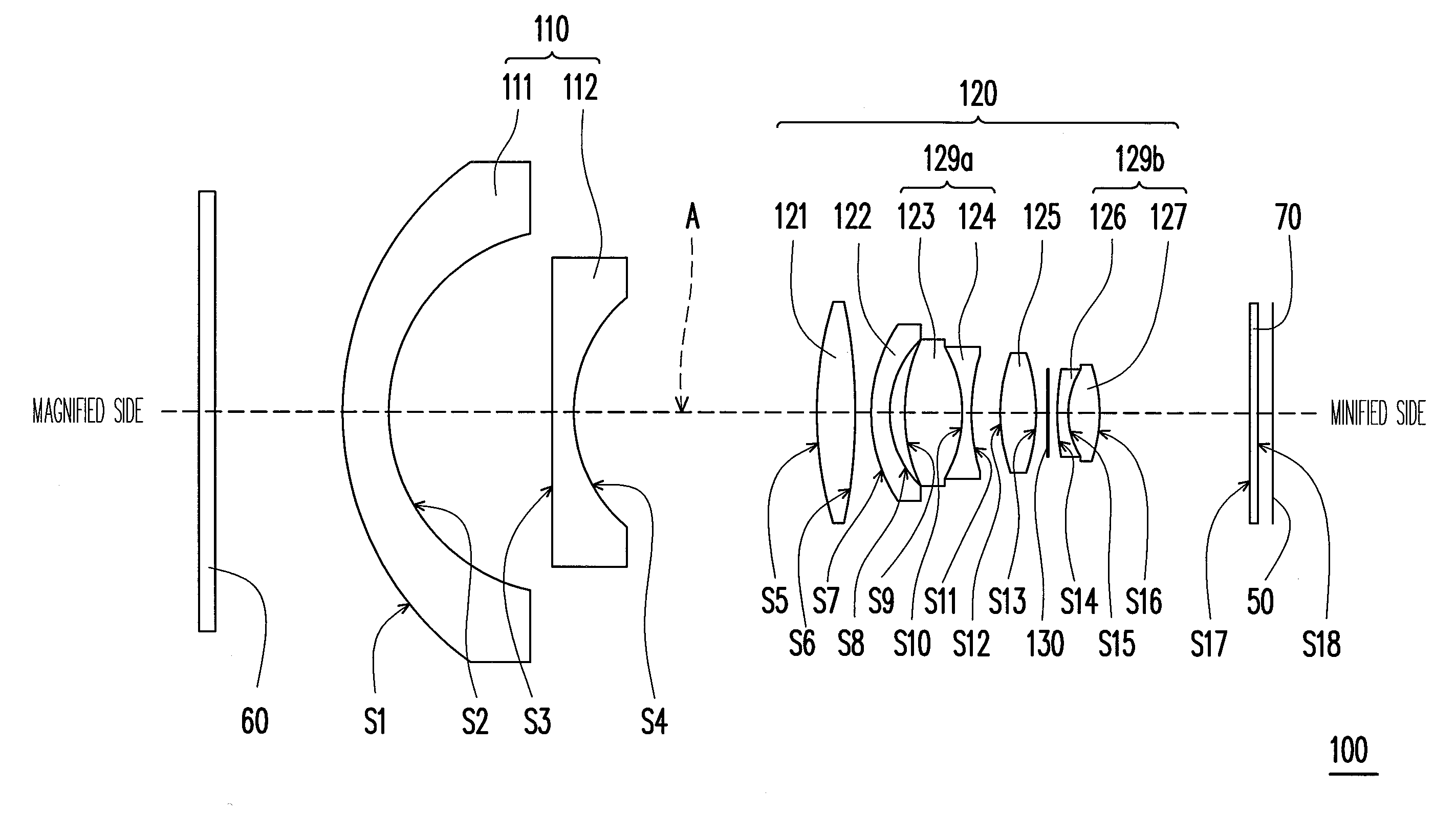
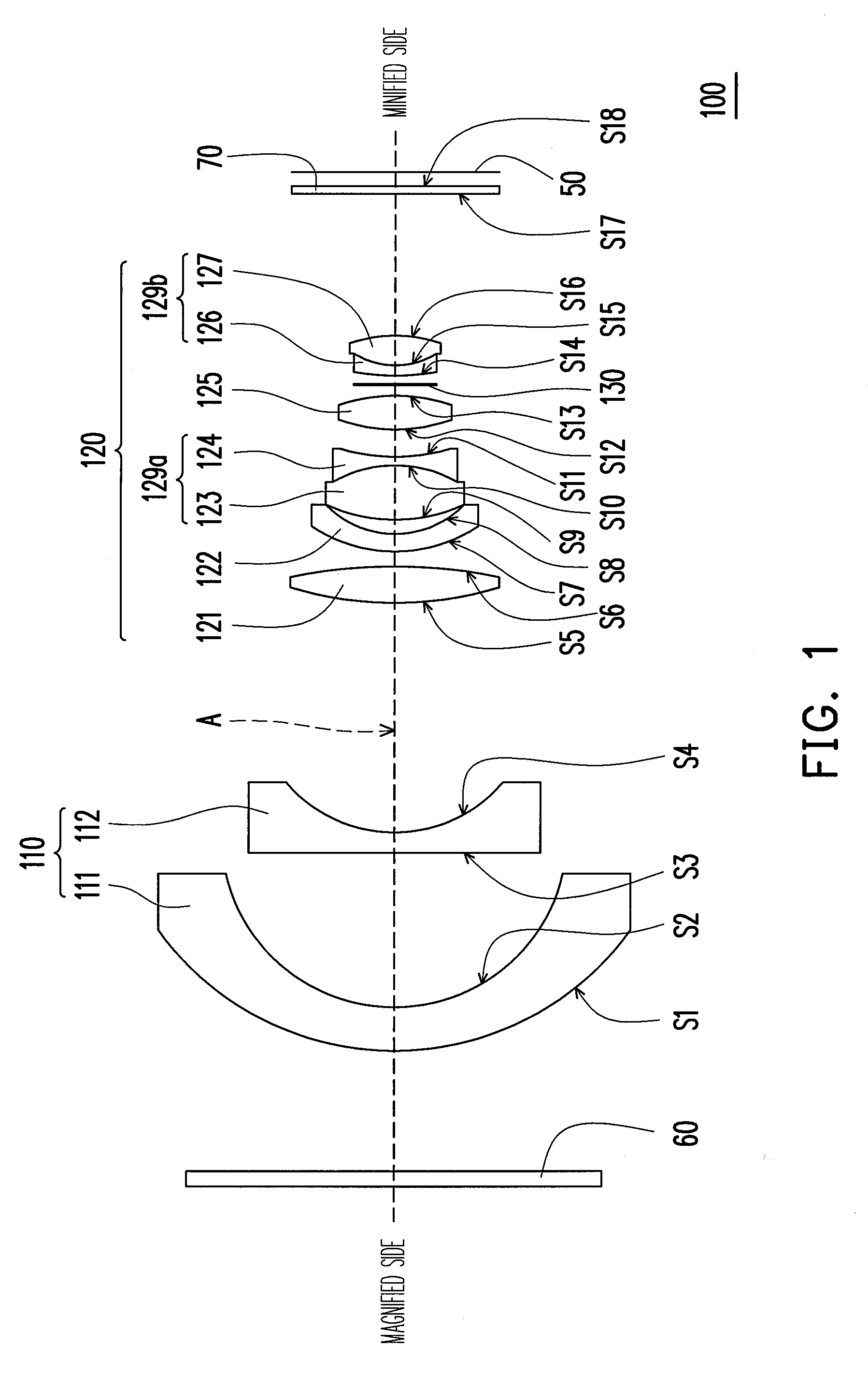
[0022]Referring to FIG. 1, a fixed-focus lens 100 of the embodiment includes a first lens group 110 and a second lens group 120. The first lens group 110 is disposed between a magnified side and a reduced side and includes a first lens 111 and a second lens 112 arranged in sequence from the magnified side to the reduced side. The refractive powers of both the first lens 111 and the second lens 112 are negative, the first lens 111 is an aspheric lens and the second lens 112 is a spherical lens. In the embodiment, the first lens 111 is, for example, a convex-concave lens with a convex surface facing the magnified side, and the second lens 112 is, for example, a plane-concave lens with a plane surface facing the magnified side.

[0023]The second lens group 120 is disposed between the first lens group 110 and the reduced side and includes a third lens 121, a fourth lens 122, a fifth lens 123, a sixth lens 124, a seventh lens 125, an eighth lens 126, and a ninth lens 12...

second embodiment

The Second Embodiment

[0037]Referring to FIG. 3, the fixed-focus lens 100′ of the embodiment is similar to the fixed-focus lens 100 in the first embodiment (as shown by FIG. 1), and the differences between them are as follows. In this embodiment, the first lens group 110′ of the fixed-focus lens 100′ further includes a tenth lens 113 disposed between the second lens 112′ and the third lens 121. The second lens group 120′ further includes an eleventh lens 128 disposed between the third lens 121 and the fourth lens 122. The refractive powers of the tenth lens 113 and the eleventh lens 128 are, for example, respectively negative and positive, and the tenth lens 113 and the eleventh lens 128 are both spherical lenses. In the embodiment, the relative position between the third lens 121 and the eleventh lens 128 is unchanged, and the third lens 121 and the eleventh lens 128 are capable of moving relatively to the fixed-focus lens 100′ for focusing. In the embodiment, the second lens 112′ i...

third embodiment

The Third Embodiment

[0043]Referring to FIG. 4, the fixed-focus lens 100″ of the embodiment is similar to the fixed-focus lens 100 in the first embodiment (as shown by FIG. 1), and the differences between them are as follows. In this embodiment, the first lens group 110″ of the fixed-focus lens 100″ further includes a tenth lens 113′ disposed between the second lens 112″ and the third lens 121. The second lens group 120″ further includes an eleventh lens 128′ disposed between the third lens 121 and the fourth lens 122. The refractive powers of the tenth lens 113′ and the eleventh lens 128′ are, for example, respectively negative and positive, and the tenth lens 113′ and the eleventh lens 128′ are both spherical lenses. In this embodiment, the positions of the first lens group 110″, the fifth lens 123, the sixth lens 124, the seventh lens 125, the eighth lens 126 and the ninth lens 127 relative to the fixed-focus lens 100″ remain unchanged, the relative positions between the third len...


PUM


Abstract

A fixed-focus lens including a first lens group and a second lens group is provided. The first lens group is disposed between a magnified side and a reduced side and includes a first lens and a second lens arranged in sequence from the magnified side to the reduced side. The refractive powers of both the first lens and the second lens are negative, and the first lens is an aspheric lens. The second lens group is disposed between the first lens group and the reduced side and includes a third lens, a fourth lens, a fifth lens, a sixth lens, a seventh lens, an eighth lens, and a ninth lens arranged in sequence from the magnified side to the reduced side. The refractive powers of the seven lenses from the third lens to the ninth lens are respectively positive, negative, positive, negative, positive, negative, and positive in sequence.

Description

CROSS-REFERENCE TO RELATED APPLICATION[0001]This application claims the priority benefit of Taiwan application serial no. 98112555, filed on Apr. 15, 2009. The entirety of the above-mentioned patent application is hereby incorporated by reference herein and made a part of this specification.BACKGROUND OF THE INVENTION[0002]1. Field of the Invention[0003]The invention generally relates to a lens, and more particularly, to a fixed-focus lens.[0004]2. Description of Related Art[0005]Along with the development of display technology, a new generation of displays, such as liquid crystal display (LCD), plasma display panel (PDP) and projection apparatus, gradually substitute traditional cathode ray tub (CRT), wherein the flat displays such as LCD and PDP occupy a larger portion in the household appliances market due to the thinner figure thereof. On the other hand, the projection apparatus keeps occupy a considerable portion in the market due to the capability of providing a mega-size fram...

Claims


Application Information

Patent Timeline
Patent Type & Authority Applications(United States)
IPC IPC(8): G02B13/18
CPCG02B13/18G02B13/16
Inventor SU, YUAN-HUNGTSENG, CHIEN-HSIUNGKANG, YI-HAO
Owner YOUNG OPTICS
Learn More