Integrated structure for optical refractor

Inactive Publication Date: 2010-10-21
广东佳兆业佳云科技股份有限公司
View PDF3 Cites 48 Cited by
  • Summary
  • Abstract
  • Description
  • Claims
  • Application Information

AI Technical Summary

Benefits of technology

[0006]A primary objective of the present invention, taking into consideration convenient maintenance and free replacement of a light emitting crystal and modulation of the wavelength and refraction angle, uses an optical refractor provided with a male end clasping portion, and uses the male end clasping portion to enable dry operational clasping to achieve easy assembly and disassembly, and enable free replacement to provide different optical specificatio

Problems solved by technology

However, using such gouging means damages the surface of the circuit board, even the electric circuit, and implementation of such means is difficult.
Furthermore, such an illumination apparatus is often seen fitted in ceilings or at relatively high positions, and thus maintenance must be

Method used


Image

  • Integrated structure for optical refractor
  • Integrated structure for optical refractor
  • Integrated structure for optical refractor

Examples


Embodiment Construction

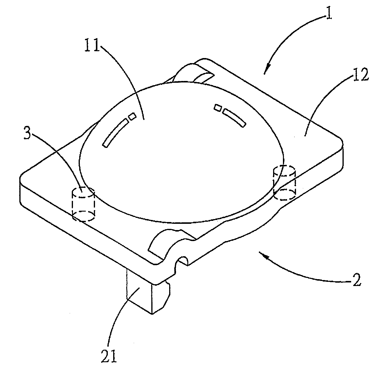
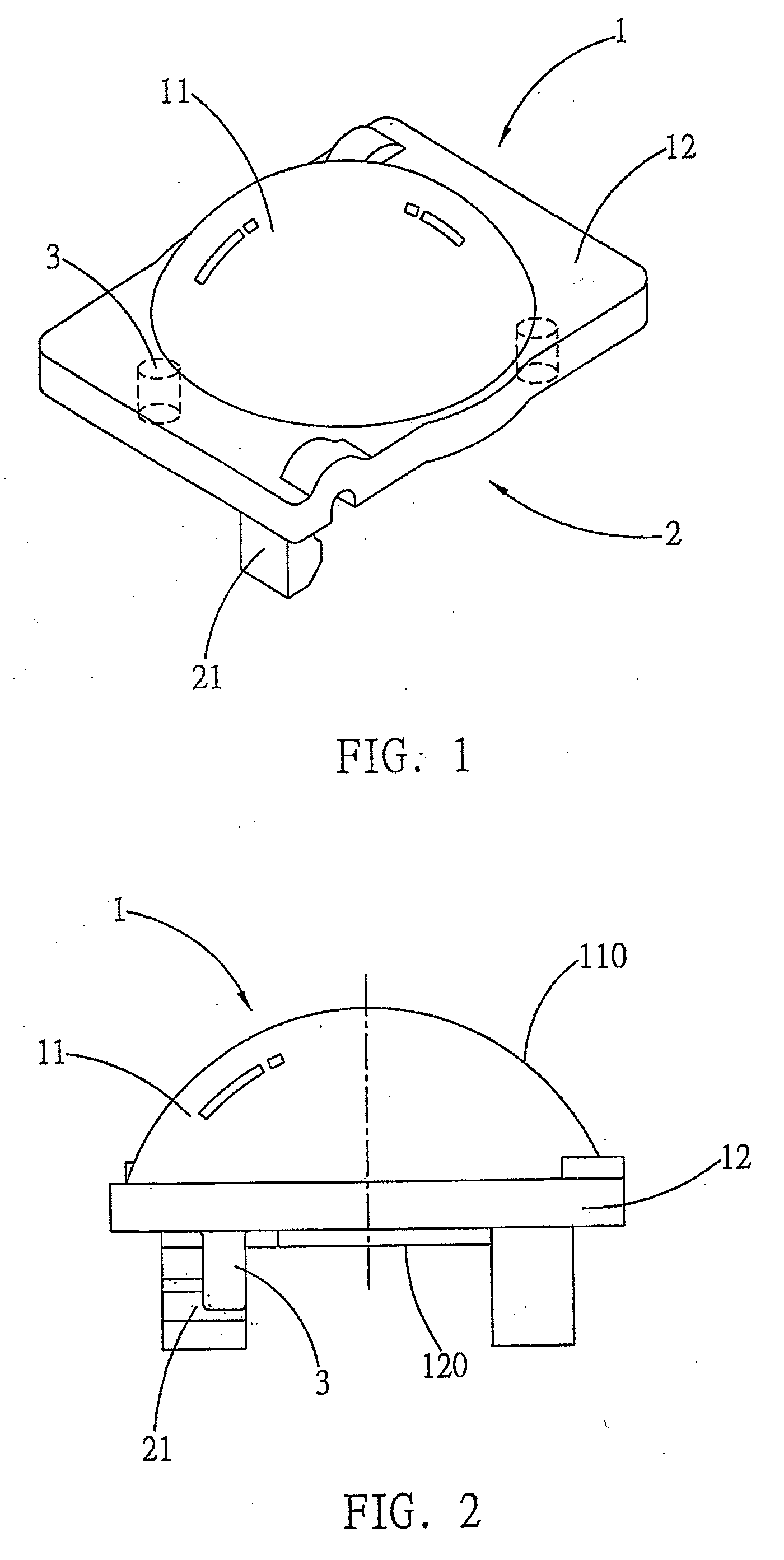
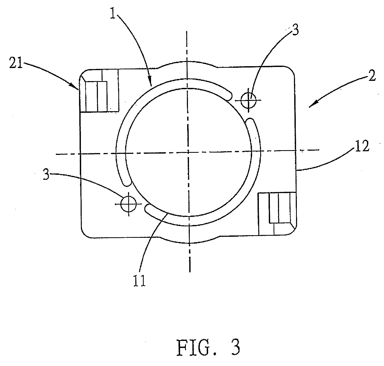
[0017]The present invention provides an integrated structure for an optical refractor, and more particularly provides an integrated structure for an optical refractor which allows exposure of crystals on a circuit board for replacement and repair, and enables free replacement to provide different specifications according to requirements for different index of refraction or wavelength.

[0018]Regarding the structure and operational principle of the present invention, referring first to FIGS. 1˜3, wherein an optical refractor 1 comprises a tabular baseplate 12, an optical refractor lens 11 pointing upward and joined to the baseplate 12, and a male end clasping portion 2 formed facing downward therefrom. The entire body can be achieved using a combination method or formed using a single body injection method, wherein an incident light surface 120 is provided at the bottom portion of the baseplate 12 corresponding to position of the axis center of optical paths, thereby enabling a light b...


PUM


Abstract

The present invention relates to an integrated structure for an optical refractor, and more particularly to an integrated structure between a circuit board and an optical refractor which enables exposing the light source after dismantling to facilitate replacement and maintenance thereof.
The integrated structure is composed of a planar baseplate, centrally integrated with an optical refractor lens, and the bottom surface of the baseplate is provided with a male end clasping portion parallel to the incident light surface, the male end clasping portion being further provided with position fixing tenons used for fixing position and clasp pins used for clasping, thereby enabling convenient disassembly and replacement to facilitate exposing the light emitting crystal on the front surface of the circuit board to enable maintenance and replacement.

Description

BACKGROUND OF THE INVENTION[0001](a) Field of the Invention[0002]The present invention provides an integrated structure for an optical refractor, and more particularly provides an integrated structure between a circuit board and an optical refractor which enables dismantling the optical refractor to expose the light emitting crystal for replacement and maintenance thereof, and facilitates replacing the optical refractor and light emitting crystal to accommodate requirements for different index of refraction or wavelength.[0003](b) Description of the Prior Art[0004]An optical refractor joined to a diode light source enables changing the light shape or illumination angle; moreover, in order to avoid diffraction loss caused by air molecules, the light emitting crystal is necessarily mounted close to the incident light surface of the optical refractor. Hence, it is often seen that a convex lens is attached close to the light-emitting surface of the light emitting crystal to enable diver...

Claims


Application Information

Patent Timeline
IPC IPC(8): F21V5/00
CPCF21K9/00F21V19/001F21V17/164H01L33/58F21V19/042F21V5/04F21V17/005F21V19/04F21Y2103/10F21Y2115/10
Inventor ZHOU, JIAN-LIN
Owner 广东佳兆业佳云科技股份有限公司
Why Eureka
Try Eureka