Apparatus and Method for Forming a Wave Form for a Stent From a Wire

a technology of wave form and stent, which is applied in the field of apparatus and method for forming the wave form of a stent, can solve the problems of forming a sten

Inactive Publication Date: 2010-10-28
MEDTRONIC VASCULAR INC
View PDF7 Cites 59 Cited by
  • Summary
  • Abstract
  • Description
  • Claims
  • Application Information

AI Technical Summary

Problems solved by technology

In view of the small size of the stents, it may be difficult to form a stent from a single wire while controlling the wave form so that the end result is a stent that expands uniformly along its length.

Method used


Image

  • Apparatus and Method for Forming a Wave Form for a Stent From a Wire
  • Apparatus and Method for Forming a Wave Form for a Stent From a Wire
  • Apparatus and Method for Forming a Wave Form for a Stent From a Wire

Examples


Embodiment Construction

[0033]The following detailed description is merely exemplary in nature and is not intended to limit the invention or the application and use of the invention. Furthermore, there is no intention to be bound by any expressed or implied theory presented in the preceding technical field, background, brief summary or the following detailed description.

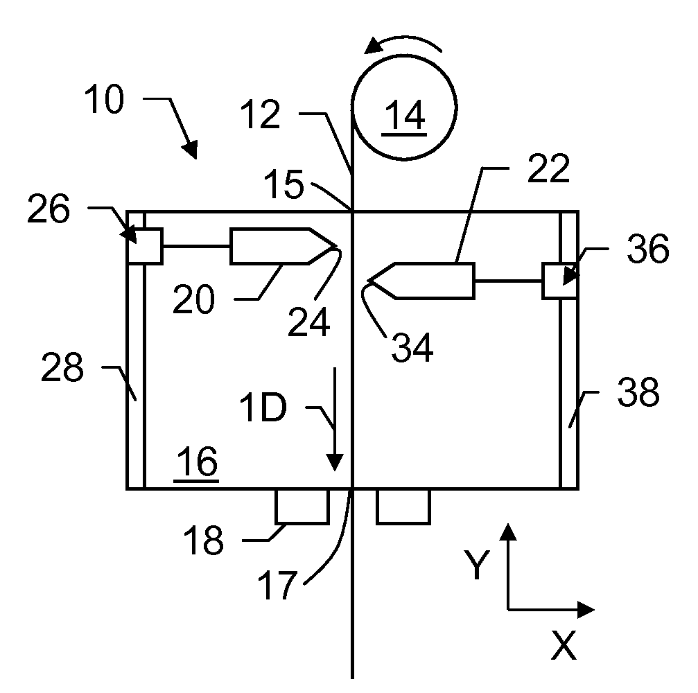
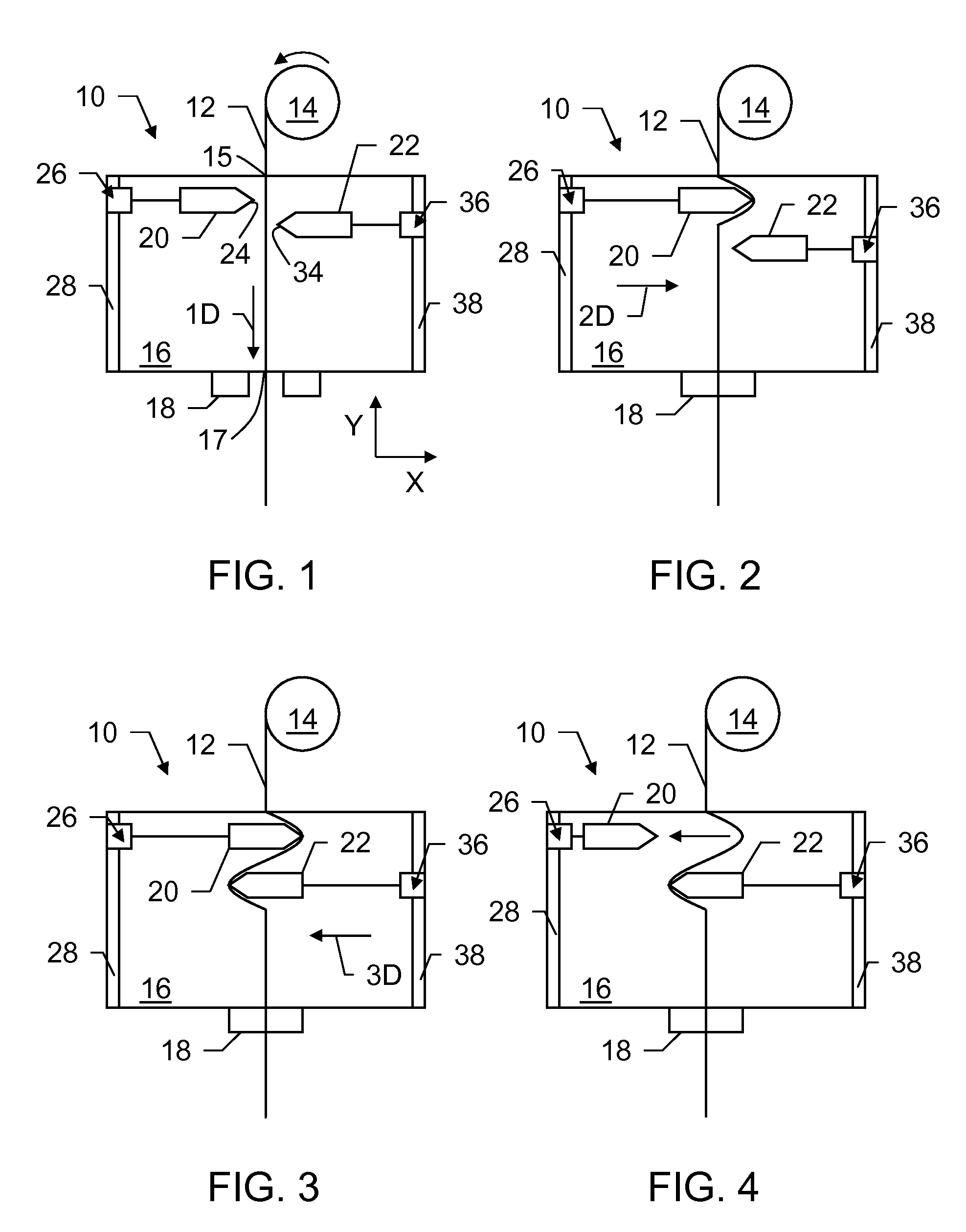
[0034]FIG. 1 schematically illustrates a portion of an apparatus 10 for forming a wave form for a stent from a wire 12. A supply 14 of the wire 12 is provided to the apparatus 10. In an embodiment, the supply 14 may include a spool upon which the wire 12 is wound. The wire 12 may have any suitable diameter for the intended stent application. In an embodiment, the wire 12 may have a diameter between about 0.0025″ and about 0.0050″.

[0035]The supply 14 may be mounted outside of the apparatus 10 or within the apparatus 10 so that the wire 12 may be fed in a first direction 1D into a wire forming area 16 of the apparatus 10 via an inlet 15. As i...


PUM

PropertyMeasurementUnit
diameteraaaaaaaaaa
timeaaaaaaaaaa
angleaaaaaaaaaa

Abstract

An apparatus for forming a wave form for a stent from a wire includes a first forming member configured to move substantially parallel to a first axis and to move substantially parallel to a second axis that is orthogonal to the first axis, and a second forming member configured to move substantially parallel to the first axis and to move substantially parallel to the second axis. The second forming member is positioned opposite from the first forming member relative to the second axis along which the wire is configured to travel. The apparatus includes a controller configured to control movement of the first forming member relative to the wire and to control movement of the second forming member relative to the wire so that the first forming member and the second forming member deform the wire in opposite directions to form a portion of the wave form.

Description

BACKGROUND OF THE INVENTION[0001]1. Field of the Invention[0002]The present invention is generally related to an apparatus and method for forming a wave form for a stent. More particularly, the present invention is related to an apparatus and method for forming the wave form from a wire.[0003]2. Background of the Invention[0004]A stent is typically a hollow, generally cylindrical device that is deployed in a body lumen from a radially contracted configuration into a radially expanded configuration, which allows it to contact and support a vessel wall. A plastically deformable stent can be implanted during an angioplasty procedure by using a balloon catheter bearing a compressed or “crimped” stent, which has been loaded onto the balloon. The stent radially expands as the balloon is inflated, forcing the stent into contact with the body lumen, thereby forming a support for the vessel wall. Deployment is effected after the stent has been introduced percutaneously, transported translumi...

Claims


Application Information

Patent Timeline
Patent Type & Authority Applications(United States)
IPC IPC(8): B21F45/00
CPCA61F2/90B21F45/008B21F1/04
Inventor HOFF, MARKMOORE, DANIELCRAVEN, MICHAELPELLEGRINI, GIANFRANCOGRISWOLD, ERIK
Owner MEDTRONIC VASCULAR INC
Why Eureka
Try Eureka