Push button switch for electric device

a push button switch and electric device technology, applied in the direction of electrical apparatus, contact operating parts, contact mechanisms, etc., can solve the problems of special fixtures, wobble between the base board and the switch button frame, and the need for special fixtures

Inactive Publication Date: 2010-10-28
FUNAI ELECTRIC CO LTD
View PDF3 Cites 35 Cited by
  • Summary
  • Abstract
  • Description
  • Claims
  • Application Information

AI Technical Summary

Benefits of technology

[0009]According to the above configured invention, since the push button piece will be kept in condition being pushed against one of the ...

Problems solved by technology

Therefore, there was a possibility of wobble between the base board and the switch button frame.
In this technology, since any covering pieces do not cover the switch base board, there was ...

Method used


Image

  • Push button switch for electric device
  • Push button switch for electric device
  • Push button switch for electric device

Examples


Embodiment Construction

[0022]Hereinafter, a first embodiment of the present invention will be described with referent to the drawings.

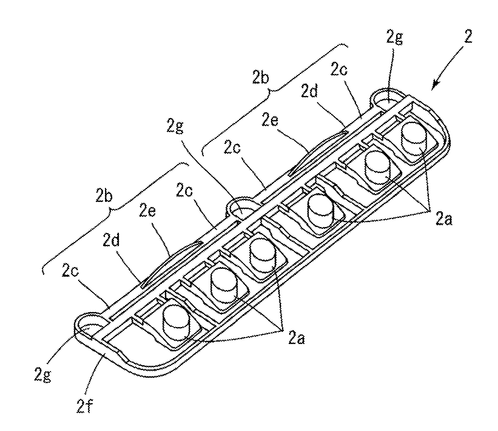
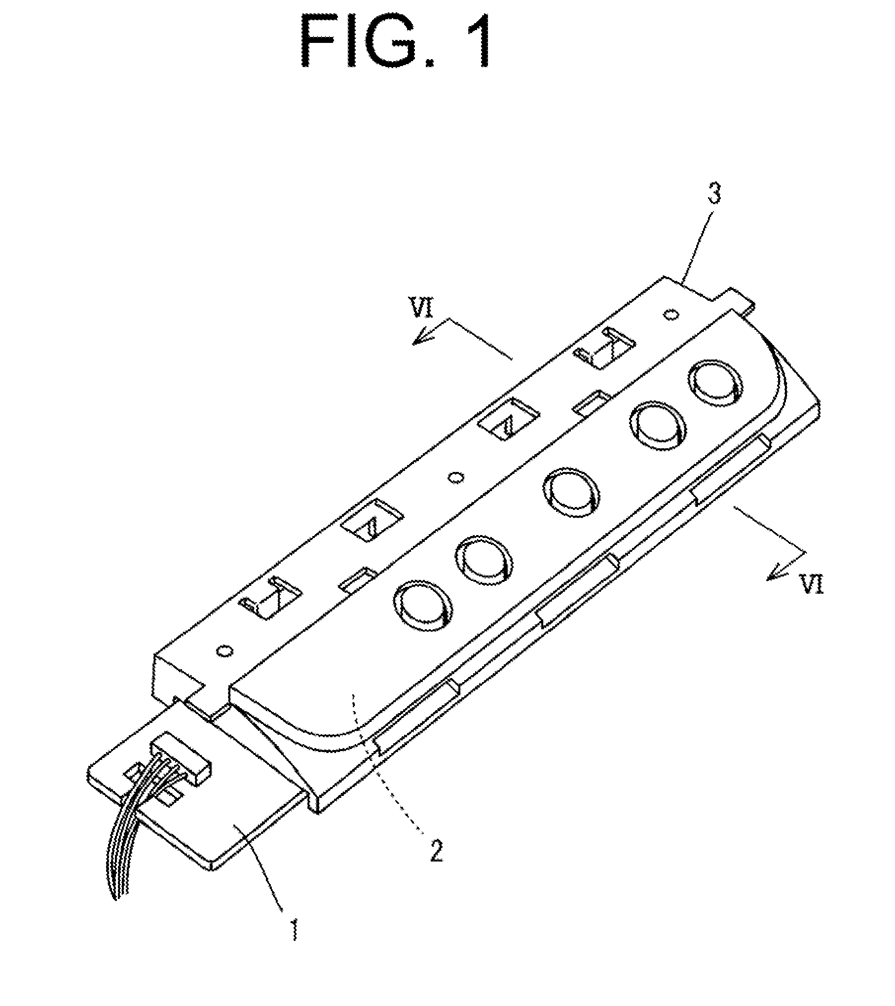
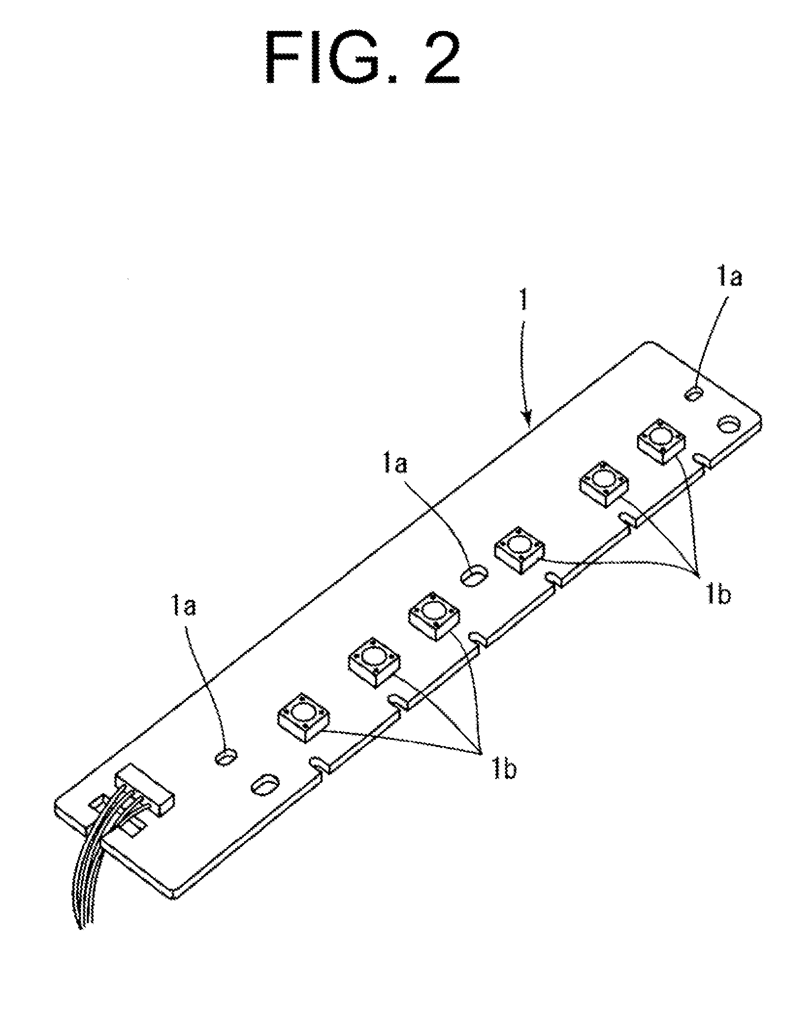
FIG. 1 shows a perspective view illustrating the assembled push button switch for electric devices according to a first embodiment of the present invention. FIG. 2 shows a perspective view of the switch board according to a first embodiment of the present invention. FIG. 3 shows a perspective view of the push button piece according to a first embodiment of the present invention. FIG. 4 shows a perspective view of the cover member according to a first embodiment of the present invention.

The push button switch for electric devices comprises a switch board 1, a push button piece 2, and a cover member 3.

The push button switch is assembled as follows. The push button piece 2 is placed on the switch board 1. Then the cover member 3 is placed on them to cover them, and is fixed to the switch board 1.

Further detailed components are explained hereinafter.

[0023]FIG. 2 shows the switc...


PUM


Abstract

When the assembly is complete, the protrusion 2e of the leaf spring 2b abuts against the bottom wall surface 3g which is an inner bottom surface of the cover member 3 and the leaf spring 2b is bent. Since the protrusion is pushed against the cover member 3, the leaf spring 2b generates force of repulsion which pushes the frame member 2f toward the opposite direction of the cover member 3. In addition, since the leaf springs 2b are aligned straightly between three bosses 3b, the leaf spring 2b pushes the push button 2 toward the switch board 1 almost in parallel. In other words, if the push button 2 is held in the cover member 3, without further components, the push button 2 is pushed against the switch board 1 and there will not be a possibility of a wobble.

Description

CROSS-REFERENCES TO RELATED APPLICATIONS[0001]The present invention contains subject matter related to and claims the benefit of Japanese Patent Application No. 2009-107862, filed in the Japan Patent Office on Apr. 27, 2009, the entire contents of which being incorporated herein by reference.BACKGROUND OF THE INVENTION[0002]1. Field of the Invention[0003]This invention relates to a push button switch for electric devices.[0004]2. Description of Related Art[0005]In a conventional technology disclosed by Japanese Patent Laid-Open No. 2000-222,970 bulletin, a catching piece is formed on a main body of electric devices. And it engages with a protruding piece of a switch button frame and fixes the switch button frame.The bulletin does not disclose relationship between a base board and a main body. Therefore, there was a possibility of wobble between the base board and the switch button frame.In a conventional technology disclosed by Japanese Patent Laid-Open No. 2006-210,220 bulletin, a ...

Claims


Application Information

Patent Timeline
IPC IPC(8): H01H13/14
CPCH01H13/7057H01H2233/042H01H2233/022H01H2233/004
Inventor YAMANAKA, TAKAHITO
Owner FUNAI ELECTRIC CO LTD
Why Eureka
Try Eureka