Radar apparatus

a technology of radar and target detection, applied in the field of radar equipment, can solve the problems of inability to reduce the possibility of pairing on noise, the accuracy of target recognition described above cannot be improved, and the “likelihood” of erroneous tracking cannot be improved, so as to enhance the continuous tracking of a real target, prevent erroneous tracking of a false target, and improve the reliability of target tracking

Inactive Publication Date: 2010-10-28
MURATA MFG CO LTD
View PDF36 Cites 20 Cited by
  • Summary
  • Abstract
  • Description
  • Claims
  • Application Information

AI Technical Summary

Benefits of technology

[0023]An object of the present invention is to provide a radar apparatus that can prevent erroneous tracking of a false target, improve reliability of target tracking and continuity of real-target tracking, and thereby prevent erroneous target recognition and improve accuracy in target recognition.

Problems solved by technology

However, when a target corresponding to a reflector in a predetermined detection area is detected and is to be tracked, there is a possibility of erroneous tracking where intangible'targets (hereinafter referred to as “false targets”) resulting from noise, as well as a tangible target (hereinafter referred to as “real target”) such as a vehicle required to be tracked, are erroneously tracked due to a reduced reception-signal strength and the effect of noise.
Thus, “likelihood” cannot improve the accuracy of the target recognition described above.
Therefore, if there is a large amount of noise, the possibility of performing pairing on noise cannot be reduced.
Thus, reliability of target tracking cannot be improved.
Moreover, if a projecting portion derived from a real target and observed in the frequency spectrum is located in an area where the effect of noise is significant, pairing cannot be performed continuously.
This results in reduced continuity of tracking of a real target.
Therefore, the reliability of target tracking and the accuracy of target recognition cannot be improved.
Therefore, the effect of noise increases the occurrence of mispairing and decreases the reliability of target tracking.

Method used


Image

  • Radar apparatus
  • Radar apparatus
  • Radar apparatus

Examples


Embodiment Construction

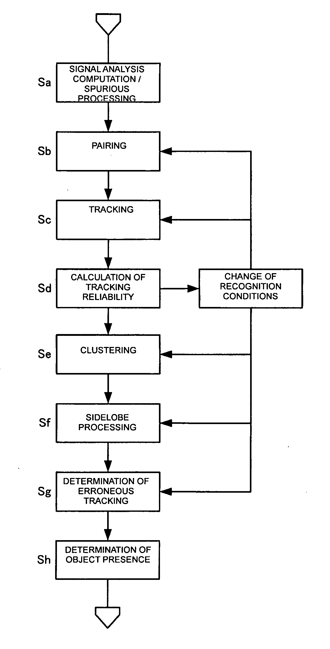
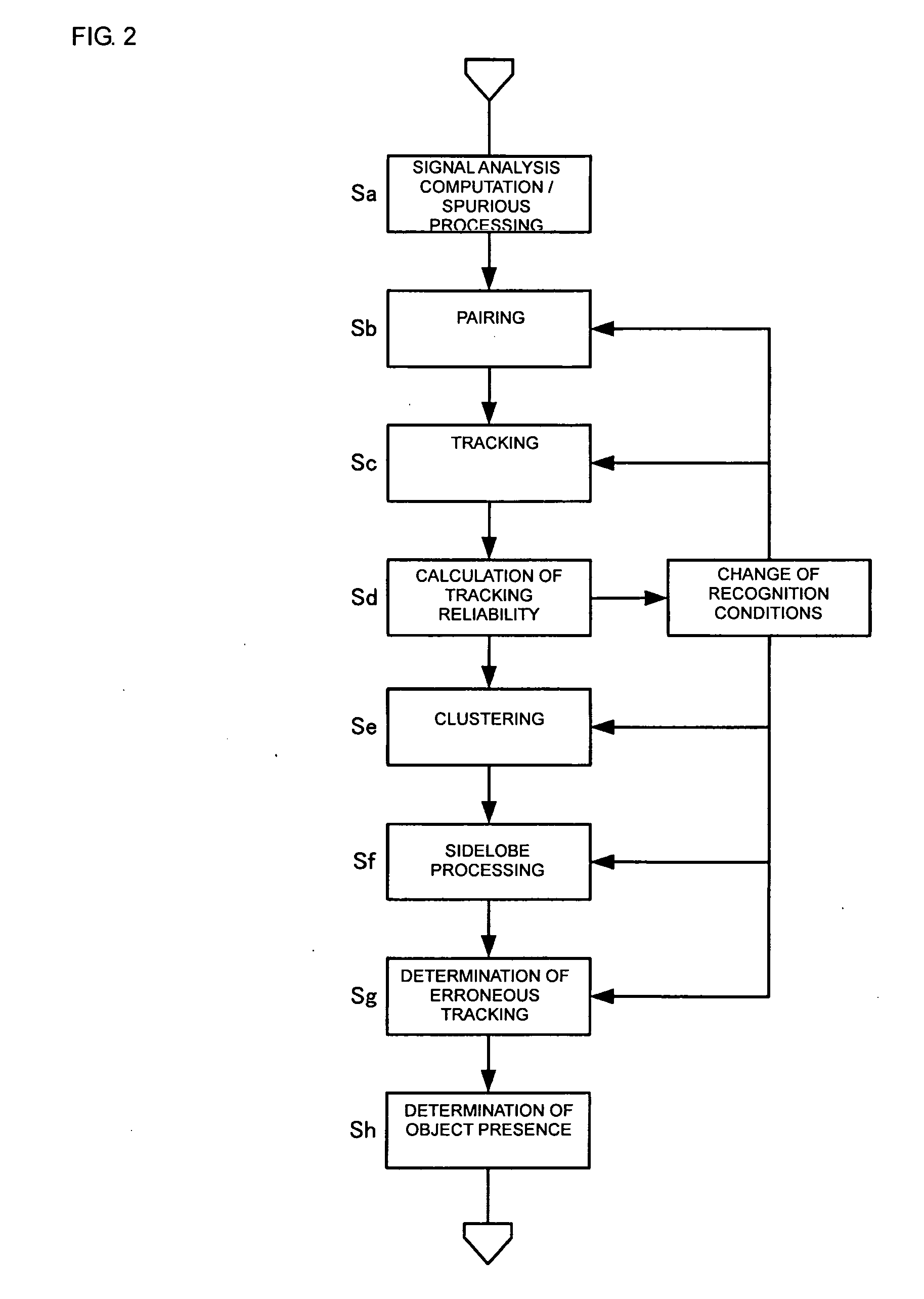
[0054]A radar apparatus according to an embodiment of the present invention will now be described with reference to the drawings.

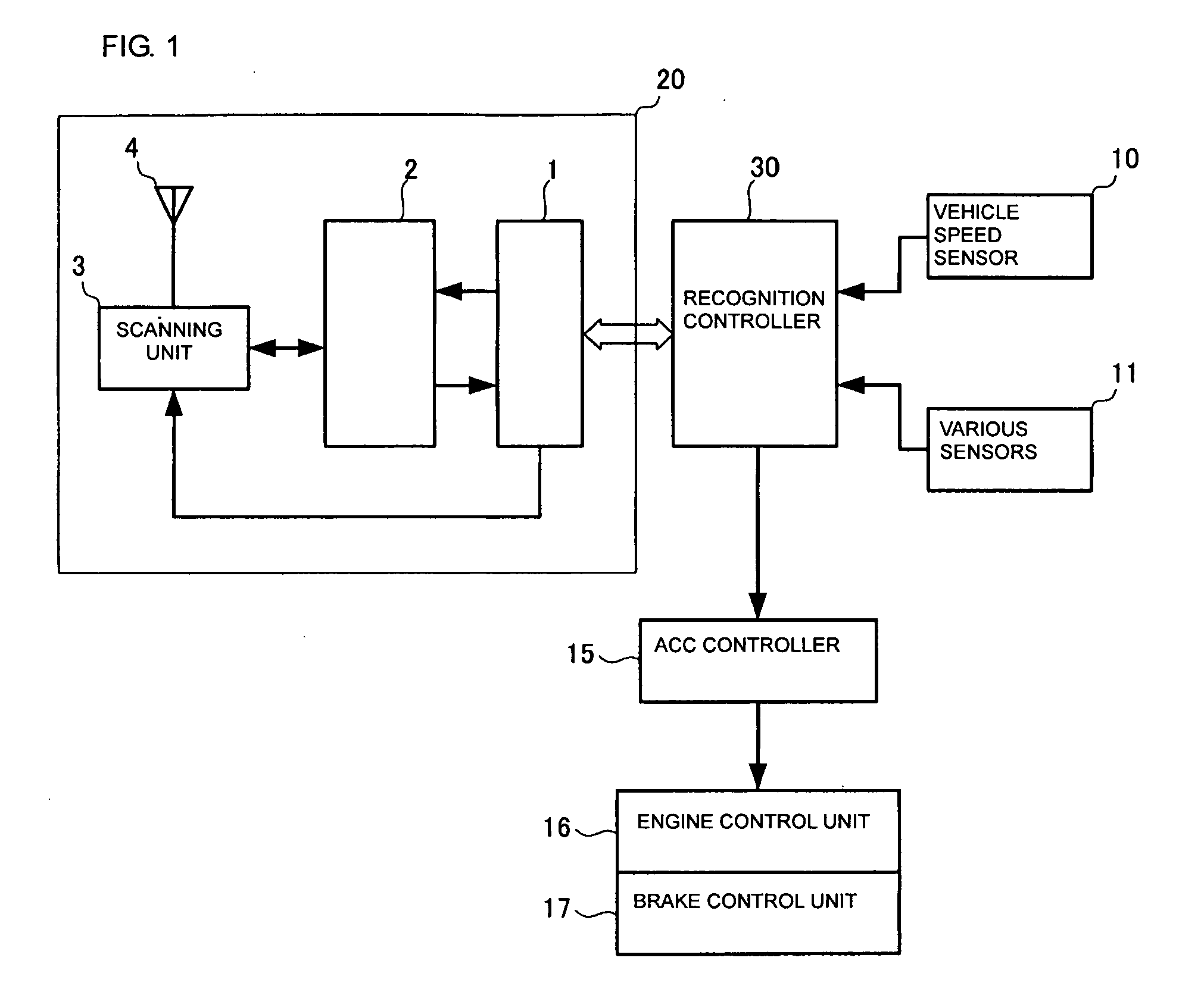
[0055]FIG. 1 is a block diagram illustrating a configuration of a system including an on-vehicle radar apparatus and various units connected thereto. Referring to FIG. 1, reference numeral 20 denotes a radar front end, which includes a control circuit 1, a millimeter wave circuit 2, a scanning unit 3, and an antenna 4. The millimeter wave circuit 2 modulates an oscillation frequency with a modulating signal supplied from the control circuit 1 as described below, and outputs a transmission signal via the scanning unit 3 to the antenna 4. Also, the millimeter wave circuit 2 supplies a reception signal, as an intermediate frequency signal (IF signal), to the control circuit 1. For example, with a mechanical reciprocating motion, the scanning unit 3 causes a beam of the antenna 4 to scan over a predetermined range.

[0056]The control circuit 1 determines the dis...


PUM


Abstract

To prevent erroneous tracking of a false target, increase reliability of target tracking, enhance continuous tracking of a real target, and thereby prevent erroneous target recognition and improve the recognition accuracy, a target is tracked on the basis of detection information that is included in detection information obtained at a plurality of different measurement time points and is estimated to have resulted from one and the same reflector; tracking reliability indicating a likelihood that a target currently being tracked has resulted from one and the same reflector is determined; and a recognition condition required for recognizing a real target is set according to the tracking reliability or its change.

Description

CROSS REFERENCE TO RELATED APPLICATIONS[0001]The present application is a continuation of International Application No. PCT / JP2005 / 012305, filed Jul. 4, 2005, which claims priority to Japanese Patent Application No. JP2004-231175, filed, Aug. 6, 2004, the entire contents of each of these applications being incorporated herein by reference in their entirety.FIELD OF THE INVENTION[0002]The present invention relates to a radar apparatus for detecting and tracking a target.BACKGROUND OF THE INVENTION[0003]An on-vehicle radar apparatus is required not only to provide the capability of detecting the distances and speeds of a plurality of reflectors in a detection area, but also, for the safety of the vehicle and other vehicles, to provide the capability of tracking a necessary target selected from a plurality of targets obtained from detection information resulting from the plurality of reflectors and noise. Such a tracking capability basically involves, from a plurality of targets detect...

Claims


Application Information

Patent Timeline
Patent Type & Authority Applications(United States)
IPC IPC(8): G01S13/66G01S13/931
CPCG01S13/345G01S13/726G01S13/931G01S2013/9353G01S2013/9325G01S2013/9346G01S2013/9339G01S2013/9329G01S2013/93185G01S2013/932
Inventor HIROGARI, YUJINAKANISHI, MOTOI
Owner MURATA MFG CO LTD
Why Eureka
Try Eureka