Projecting zoom lens and projection type display apparatus

a projecting zoom and projection type technology, applied in the direction of printers, instruments, cameras focusing arrangements, etc., can solve the problems of increasing the fno of the lens, the effect of widening the field of zoom lens, reducing the amount of variations in various aberrations, and high resolution power

Active Publication Date: 2010-10-28
FUJIFILM CORP
View PDF2 Cites 35 Cited by
  • Summary
  • Abstract
  • Description
  • Claims
  • Application Information

AI Technical Summary

Benefits of technology

[0012]The present invention aims at solving the above problems and thus it is an object of the invention to provide a projecting zoom lens capable of reducing the above-mentioned variations in the lens properties caused by the variable power and a projection type display apparatus including such projecting zoom lens.
[0029]Thanks to this structure, while maintaining a high zooming ratio, the angle of the zoom lens may be widened easily and, in the angle widened state as well, in the whole area of the power varying operation, the fastness (Fno.) may be kept substantially constant.
[0030]Therefore, according to the invention, there may be provided a projecting zoom lens of a high resolving power which may reduce variations in the properties thereof possibly caused by the power varying operation, and a projection type display apparatus including such projecting zoom lens.
[0032]Thanks to this, while attaining the object to widen the angle of field of the zoom lens, in the whole area of the power varying operation, it is possible to reduce the amounts of variations in various aberrations including spherical aberrations and astigmatism.
[0033]This makes it possible to provide a projecting zoom lens of a high resolving power which may reduce such variations in its properties possibly caused by the power varying operation, and a projection type display apparatus using such projecting zoom lens.
[0034]Further, according to the first and second projecting zoom lenses and projection type display apparatus including such projecting zoom lenses, it is possible to satisfy the request that the telecentricity of the reduction side of the lens system may be enhanced.

Problems solved by technology

On the other hand, due to such enhancement in the resolution of the light valve and the resolving power of the projecting lens, there is raised a big problem that the properties of the light valve and projecting lens in the whole zooming area ranging from a wide angle end to a tele end are caused to vary.
However, generally, when the resolving power of the lens varies from the wide angle end to the tele end, the fastness (that is, Fno.) of the lens increases, which results in the dark screen.
However, in this lens, there is raised a problem that the variable amount of spherical aberration caused when the power of the lens is varied and, especially, in the tele end, the marginal rays are large to thereby provide an under-fastness tendency.
As described above, there is found a problem that the properties of the lens are caused to vary according to the variable power: that is, when the projection distance is varied depending on the size of a projection space in a room, the image of an object cannot be projected on the screen with the same brightness; and thus, there has been increasing a request to take proper measures against this problem quickly.
Also, in the projecting zoom lens disclosed in the above JP-A-2005-84455, although the varying amount of the spherical aberration caused by the variable power is reduced, there is raised a problem that the properties of the lens are caused to vary according to the variable power: that is, the astigmatism of the lens increases.

Method used


Image

  • Projecting zoom lens and projection type display apparatus
  • Projecting zoom lens and projection type display apparatus
  • Projecting zoom lens and projection type display apparatus

Examples


example 1

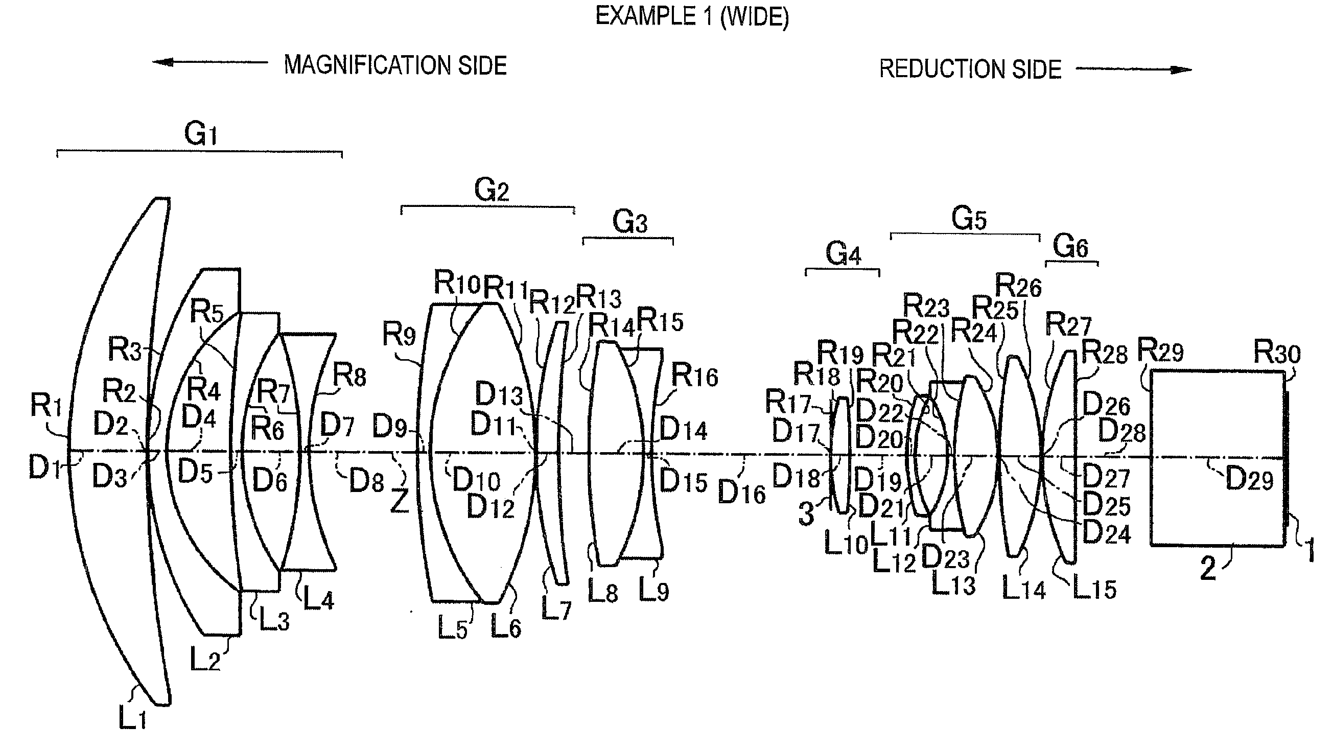
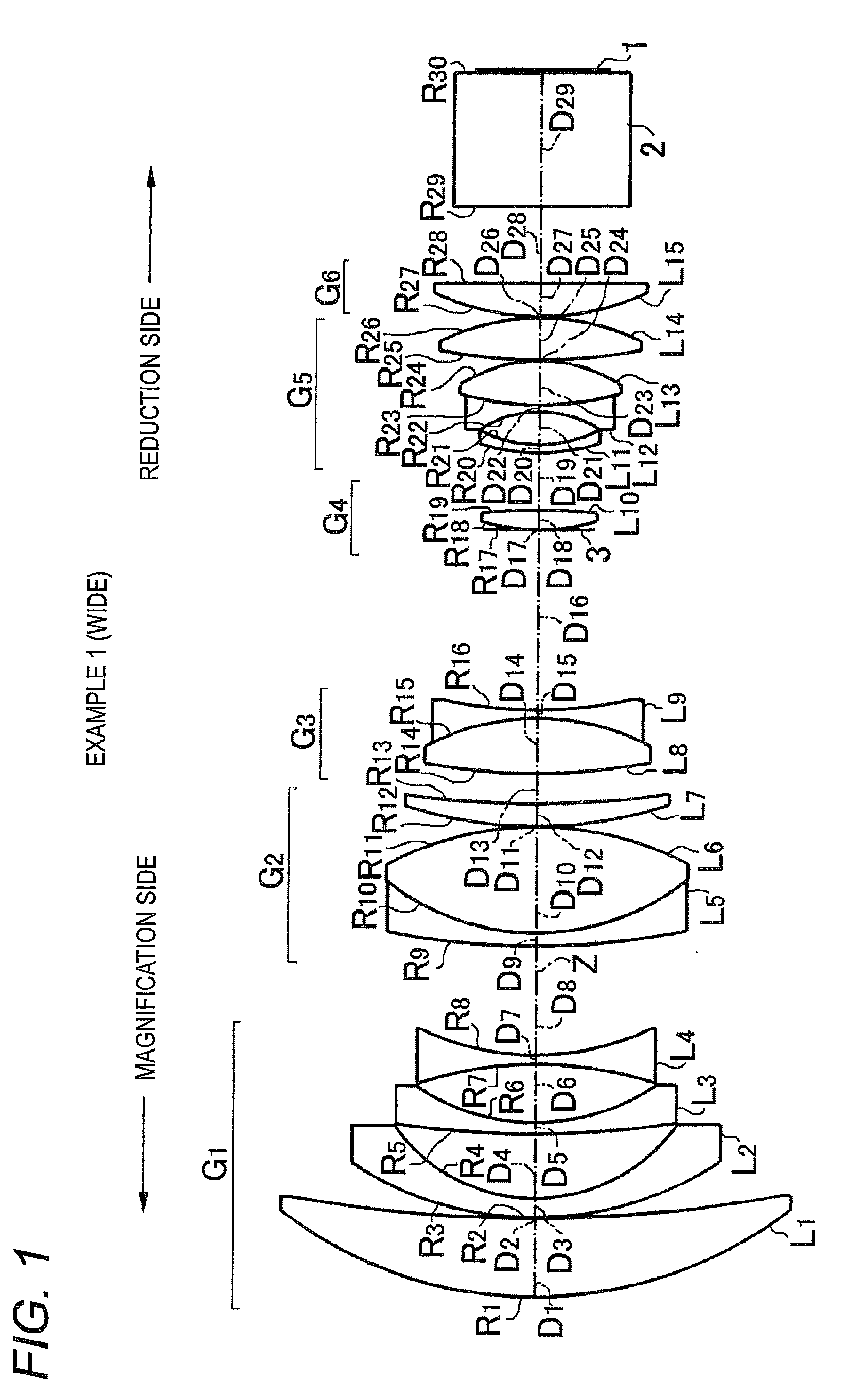
[0087]A projecting zoom lens according to the present example 1, as described above, is structured as shown in FIG. 1. That is, the first lens group G1 includes, sequentially from the magnification side, a first lens L1 made of a positive meniscus lens having a convex surface facing the magnification side, a second lens L2 made of a negative meniscus lens having a convex surface facing the magnification side, a third lens L3 made of a negative meniscus lens having a convex surface facing the magnification side, and a fourth lens L4 made of a biconcave lens. And, the second lens group G2 includes, sequentially from the magnification side, a fifth lens L5 made of a negative meniscus lens having a convex surface facing the magnification side, a sixth lens L6 made of a biconvex lens, and a seventh lens L7 made of a positive meniscus lens having a convex surface facing the magnification side, while the fifth lens L5 and sixth lens L6 are connected to each other to from a cemented lens.

[0...

example 2

[0099]FIG. 3 shows a schematic structure of a projecting zoom lens according to an example 2. Basically, this projecting zoom lens, substantially similarly to the example 1, includes six lens groups. Specifically, the respective lens groups are structured in the following manner.

[0100]Firstly, the first lens group G1 includes, sequentially from the magnification side, a first lens L1 made of a positive meniscus lens having a convex surface facing the magnification side, a second lens L2 made of a negative meniscus lens having a convex surface facing the magnification side, a third lens L3 made of a negative meniscus lens having a convex surface facing the magnification side, and a fourth lens L4 made of a biconcave lens. And, the second lens group G2 is made of a cemented lens which includes, sequentially from the magnification side, a fifth lens L5 made of a biconcave lens and a sixth lens L6 made of a biconvex lens, while the fifth and sixth lens are connected together.

[0101]Also,...

example 3

[0111]FIG. 5 shows a schematic structure of a projecting zoom lens according to an example 3. Basically, this projecting zoom lens, substantially similarly to the example 1, includes six lens groups. Specifically, the respective lens groups are structured in the following manner.

[0112]Firstly, the first lens group G1 includes, sequentially from the magnification side, a first lens L1 made of a positive meniscus lens having a convex surface facing the magnification side, a second lens L2 made of a negative meniscus lens having a convex surface facing the magnification side, a third lens L3 made of a negative meniscus lens having a convex surface facing the magnification side, a fourth lens L4 made of a negative meniscus lens having a convex surface facing the magnification side, and a fifth lens L5 made of a biconcave lens. And, the second lens group G2 includes, sequentially from the magnification side, a sixth lens L6 made of a positive meniscus lens having a convex surface facing ...


PUM


Abstract

The projecting zoom lens includes, sequentially from its magnification side, a negative first lens group, a positive second lens group, a negative third lens group, a positive fourth lens group, a positive or negative fifth lens group, and a positive six lens group, while the reduction side of the projecting zoom lens is formed as a telecentric system. When the power of the zoom lens is varied, the first lens group and sixth lens group are fixed, while the second to fifth lens groups move. In such power varying operation, the movement of the third lens group advances from the magnification side to the reduction side as the zoom lens goes from the wide angle end toward the tele end.

Description

[0001]The present application claims priority from Japanese Patent Application No. 2009-110161 filed on Apr. 28, 2009, the entire content of which is incorporated herein by reference.BACKGROUND OF INVENTION[0002]1. Field of the Invention[0003]The present invention relates to a projecting zoom lens to be mounted on a projection type display apparatus and having a six lens group structure including three or four moving lens groups, and a projection type display apparatus with such projecting zoom lens mounted thereon.[0004]2. Description of the Related Art[0005]Recently, a transmission type or a reflection type liquid crystal display apparatus and a projector apparatus (a projection type display apparatus) such as a DMD display apparatus using a light valve have been widely spread and have been enhanced in their functions. Especially, with enhancement in the resolution of the light valve, there has been increasing a request to enhance the resolving power of the projecting lens.[0006]A...

Claims


Application Information

Patent Timeline
Patent Type & Authority Applications(United States)
IPC IPC(8): G02B15/177G03B21/14
CPCG02B15/177G02B15/1465
Inventor AMANO, MASARU
Owner FUJIFILM CORP
Why Eureka
Try Eureka