Optical time domain reflectometer and method for testing optical fiber using optical pulse

a technology of optical fiber and reflectometer, which is applied in the direction of optical apparatus testing, instruments, structural/machine measurement, etc., can solve the problems of difficult to meet such kinds of desires, difficult to take satisfactory real-time measurements, and difficult to accurately measure reflection attenuation, etc., and achieve the effect of easy real-time measuremen

Active Publication Date: 2010-10-28
ANRITSU CORP
View PDF10 Cites 11 Cited by
  • Summary
  • Abstract
  • Description
  • Claims
  • Application Information

AI Technical Summary

Benefits of technology

[0129]As a result, according to the optical time domain reflectometer of the present invention and the method for testing optical fiber using an optical pulse of the present invention, the reflection attenuation where the level difference between objects to be measured is large can be measured easily in real time.
[0130]Further, according to the optical time domain reflectometer of the present invention and the method for testing optical fiber using an optical pulse of the present invention, at the time of the real-time measurement, a operator does not have to manually adjust the attenuator (gain and attenuation) according to the waveform level, and the operator merely has to move any marker to the target position on the display screen if necessary, so as to observe the waveform on the desired position with the S / N ratio of not less than the predetermined value.
[0131]According to according to the optical time domain reflectometer of the sixth aspect of the present invention and the method for testing optical fiber using an optical pulse of the thirteenth aspect of the present invention, in the real-time measurement, when the attenuators are set for the plurality of markers, the measurement frequency can be changed according to the fluctuation in the level on the waveform position specified by the marker, and when the fluctuation in the level on the waveform position specified by the marker is small, the measurement frequency is lowered, and when the fluctuation in the level is large, the measurement frequency is temporarily raised, so that the change in the measurement waveform can be quickly and easily catched.

Problems solved by technology

Since it takes a certain amount of time to measure the reflection attenuation in the averaging measurement, when it is clear that the measurement result of the reflection attenuation deviates from an acceptable range, frequently the fusing operator performs the fusing operation for a subsequent optical fiber, and thus the measurement and the fusion cannot take place simultaneously.
Therefore, in the conventional optical pulse tester (OTDR) 49 shown in FIG. 9, it is very difficult to take satisfactory real-time measurement including the measurement of the reflection attenuation under such a circumstance.
Therefore, in the real-time measurement shown in FIGS. 12 and 13, in any case, it is difficult to accurately measure the reflection attenuation.
In the conventional optical pulse tester (OTDR) 49 shown in FIG. 9, in the real-time measurement, it is extremely difficult to comply with such kinds of desires because of the above-mentioned many problems.

Method used


Image

  • Optical time domain reflectometer and method for testing optical fiber using optical pulse
  • Optical time domain reflectometer and method for testing optical fiber using optical pulse
  • Optical time domain reflectometer and method for testing optical fiber using optical pulse

Examples


specific embodiment

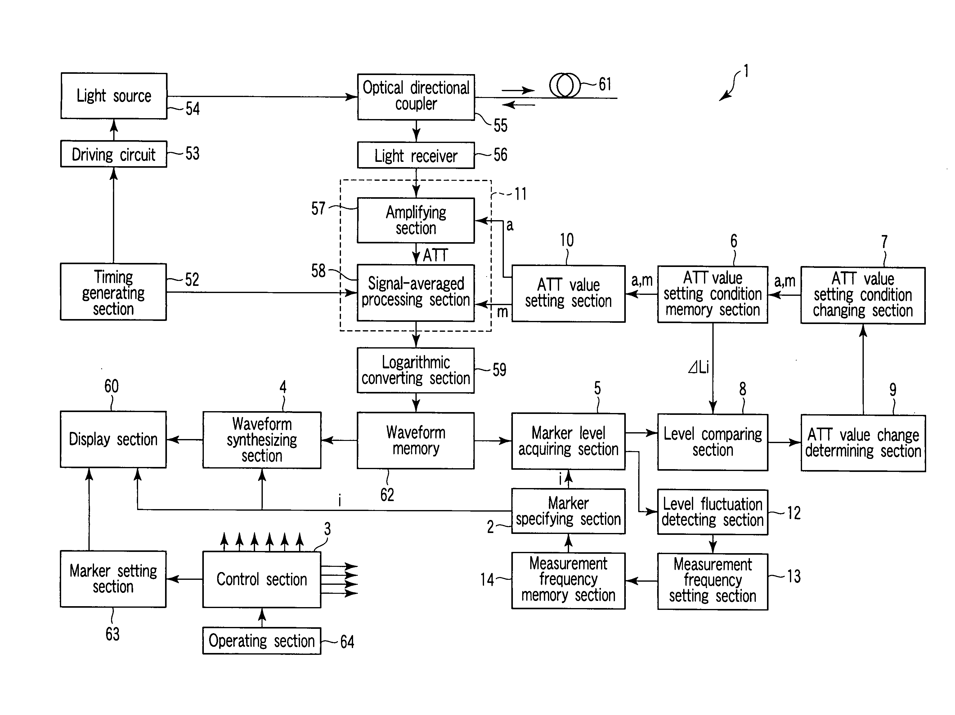
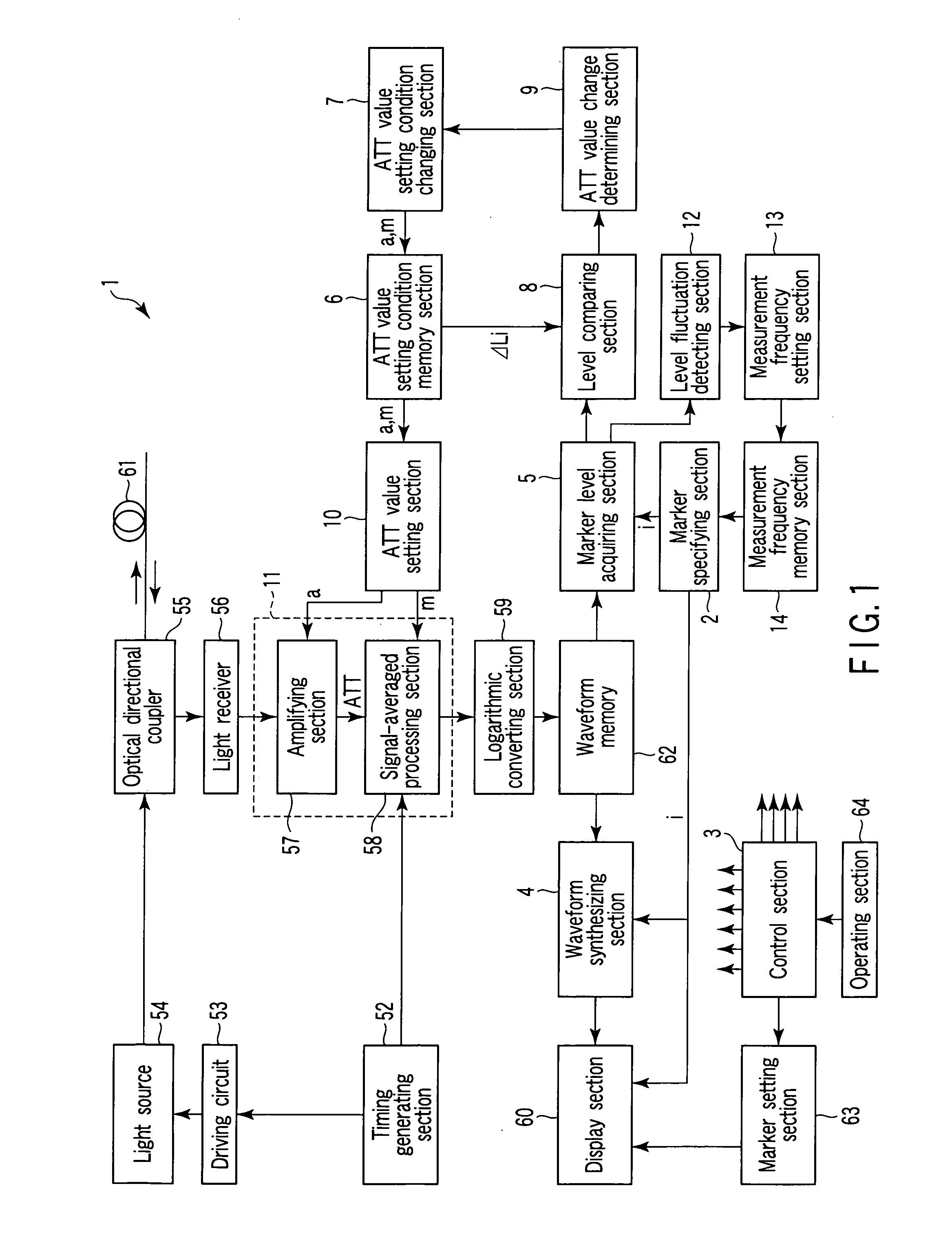
[0190]A specific embodiment of the optical pulse tester (OTDR) to which the optical time domain reflectometer (OTDR) and the method for testing optical fiber using an optical pulse of the present invention are applied will be described below with reference to FIG. 1.

[0191]As is clear from the description of the basic configuration, the optical pulse tester (OTDR) 1 as the specific embodiment to which the optical time domain reflectometer and the method for testing optical fiber using optical pulse of the present invention are applied includes a measurement level changing function of automatically and selectively setting optimum attenuator (ATT) values in cooperation with a marker position specified on the measurement waveform by a operator on the display screen, and changing the measurement level so that the measurement waveform can be observed with a good S / N ratio of not less than the predetermined value in the real-time measurement.

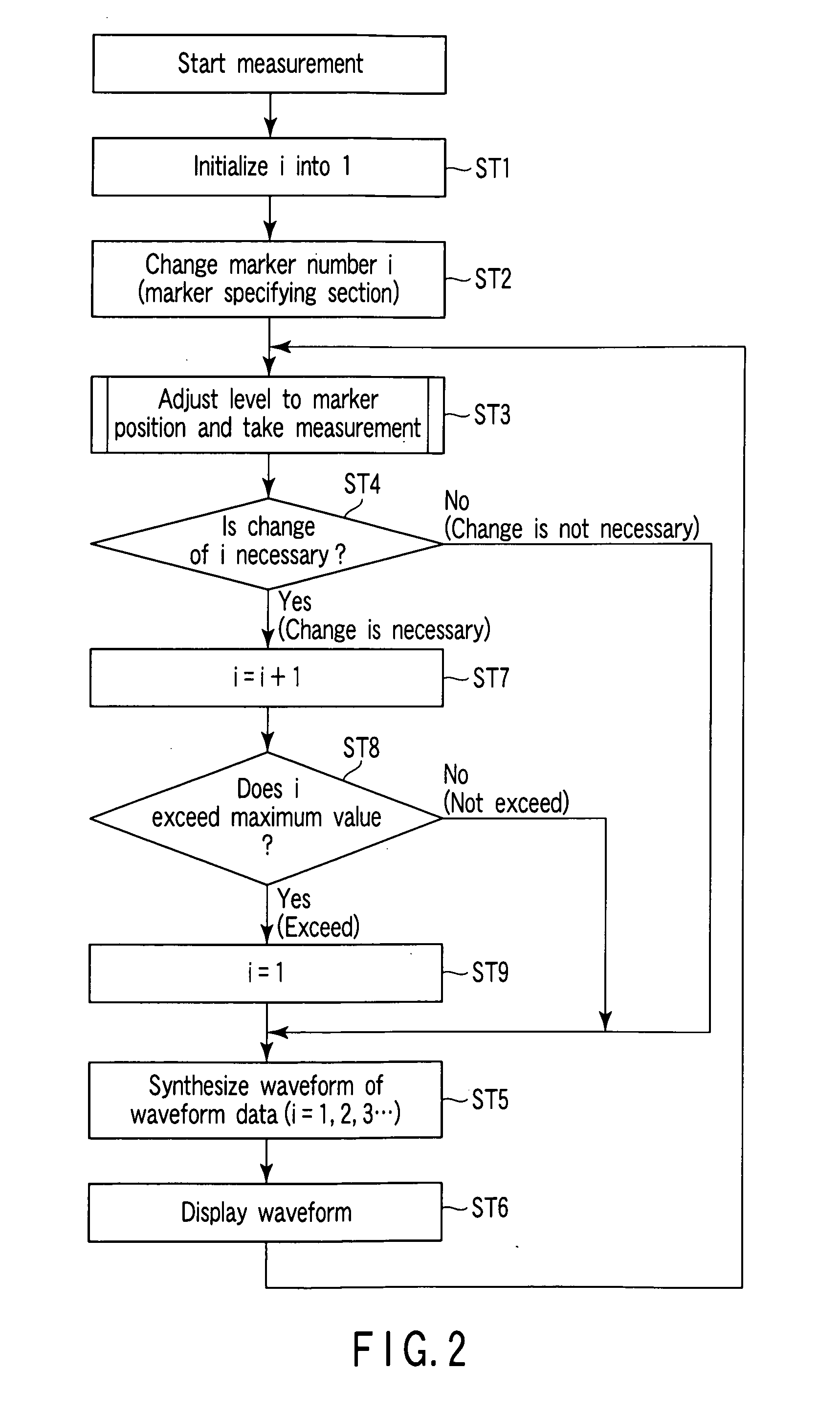
[0192]The measurement level changing function in...


PUM

PropertyMeasurementUnit
signal-to-noise ratioaaaaaaaaaa
frequencyaaaaaaaaaa
electricaaaaaaaaaa

Abstract

When a measurement position is specified by a marker during real time measurement, a marker level acquisition unit acquires a waveform level from waveform data stored in a waveform memory. A level comparison unit judges whether the waveform level acquired by the maker level acquisition unit is within an effective measurement level range set in accordance with a currently selected attenuator (ATT) value. If the level comparison unit judges that the waveform level is out of the effective measurement level range, an ATT value modification unit modifies the ATT value to a new ATT value so that the waveform level is contained in the corresponding effective measurement level range. According to the new ATT value, a control performs measurement of an optical fiber to be measured so that a waveform can be observed with a preferable SN ratio above a predetermined value according to the measured waveform displayed on a screen of a display unit.

Description

TECHNICAL FIELD[0001]The present invention relates to an optical time domain reflectometer and a method for testing optical fiber using an optical pulse, and particularly to an optical time domain reflectometer (OTDR) as an optical pulse tester which allows an optical pulse to be incident on a measured optical fiber, detects a fault point position of the measured optical fiber based on a detection result of reflected light returned from the measured optical fiber according to the incidence of the optical pulse, and measures a transmission loss property and a connection loss property of the measured optical fiber, and a method for testing an optical fiber using an optical pulse.BACKGROUND ART[0002]Optical time domain reflectometers (OTDR) as optical pulse testers emit optical pulse to be incident on a measured optical fiber, detect reflected light returned from the measured optical fiber according to the incidence of the optical pulse, so as to detect a fault point position of the me...

Claims


Application Information

Patent Timeline
Patent Type & Authority Applications(United States)
IPC IPC(8): G01M11/00G01N21/00
CPCG01M11/3145
Inventor HORI, SHIGEO
Owner ANRITSU CORP
Why Eureka
Try Eureka