System and method for calculating flight predictions by vertical sections

a technology of flight prediction and vertical section, applied in the field of flight management systems, can solve the problems of inability to systematically limit the prediction horizon to a flight leg, inability to use real-time algorithms to determine the order in which constraints must be applied, and inability to achieve the perfective maintenance capabilities of applications, so as to facilitate the breaking down of issues and responsibilities, the effect of enhancing the perfective maintenance capabilities

Active Publication Date: 2013-08-13
THALES SA
View PDF29 Cites 2 Cited by
  • Summary
  • Abstract
  • Description
  • Claims
  • Application Information

AI Technical Summary

Benefits of technology

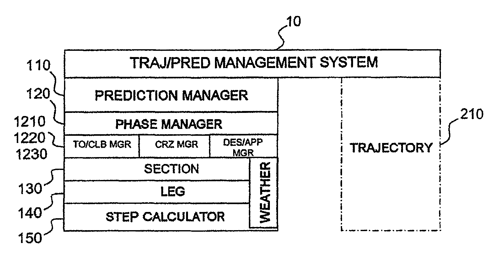
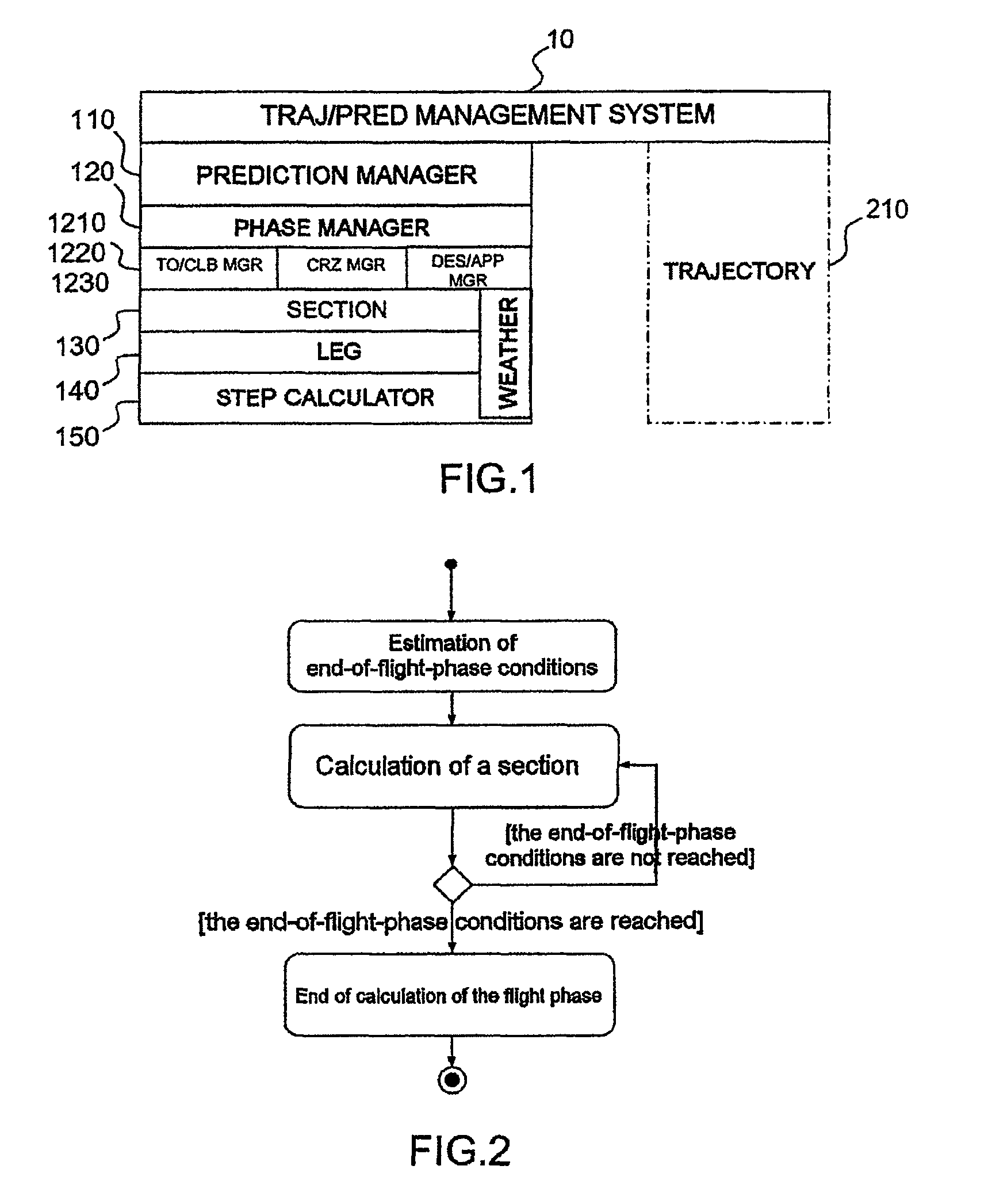
[0004]The present invention resolves this problem by providing, between the phase and the leg, a horizon for calculating the predictions that can be used to resolve the constraints easily in real time.
[0015]The invention also offers the advantage of facilitating the breaking down of the issues and responsibilities at the software specification and development level. Furthermore, the calculation architecture is thus more modular with the possibility of adding methods for resolving new constraints without modifying the architecture. Thus, the perfective maintenance capabilities of the application are greatly enhanced.

Problems solved by technology

In particular, when there are numerous waypoints, it is impossible to use an algorithm running in real time to determine the order in which the constraints must be applied.
This order must therefore be selected arbitrarily, which necessarily leads to errors.
On the other hand, it is not possible to systematically limit the prediction horizon to a flight leg, since one of the objectives of the calculations is to determine the appropriate transitions for passing from one leg to another taking into account the characteristics of the subsequent legs.

Method used


Image

  • System and method for calculating flight predictions by vertical sections
  • System and method for calculating flight predictions by vertical sections
  • System and method for calculating flight predictions by vertical sections

Examples


Embodiment Construction

[0029]Unless stated otherwise, in the description and the figures, the symbols, acronyms and abbreviations have the meanings indicated in the table below.

[0030]

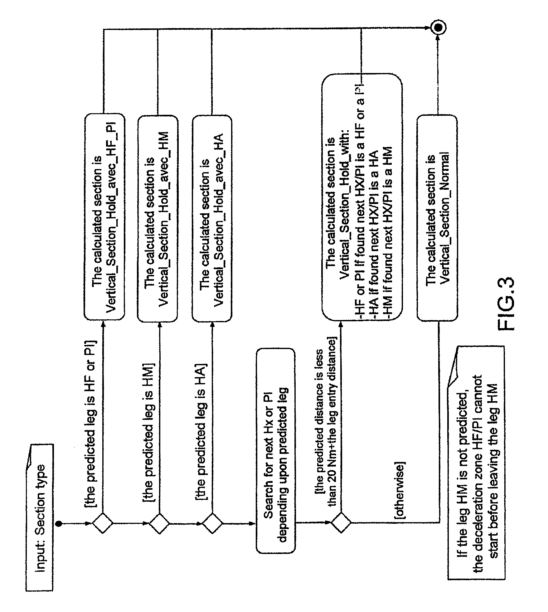
Symbol / abbreviationMeaningAFDXAvionics Full DupleX switched EthernetAMSAvionics Management SystemAPPApproachARINCAeronautical Radio, Inc.CASCalibrated Air SpeedCLBClimbCRZCruiseDESDescentDMEDistance Measuring EquipmentENVUML representation of the external environmentFIXWaypoint or characteristic fixed point in aflight planFMSFlight Management SystemFPLNFlight PlanGNSSGlobal Navigation Satellite SystemHAHold to AltitudeHFHold to FixHMHolding Manual legHOLD / HxHolding patternICAO / OACIInternational Civil Aviation AuthorityIMAIntegrated Modular AvionicsKTSKnots - Unit of speed: one knot = 1 nautical mileper hour = 1.852 km / hMEAMinimum Altitude in flight or in RouteMOCAMinimum Obstacle Clearance AltitudeNMNautical Miles (1 NM = 1.856 km)PIProcedure TurnPREDPredictionTLTOTactical Landing Take-OffTOTake-OffTRAThrust Reduction Altitud...


PUM


Abstract

The invention relates to a system and a method for calculating flight predictions of an aircraft in which an intermediate prediction horizon is defined between the flight phase and the leg. This horizon, that is called vertical section, is defined such that the limit conditions that are applicable to it, for example the target speed, target altitude, characteristic altitude and maximum end-of-section distance, are valid for the entire vertical section. Thus, it is not necessary, in calculations to check the compatibility of the flight parameters with the applicable constraints, to arbitrarily select the constraint that must be given priority. Furthermore, this intermediate level architecture allows for a greater modularity of the prediction management software and therefore a greater factorization of the developments and greater ease of maintenance.

Description

CROSS-REFERENCE TO RELATED APPLICATIONS[0001]This application claims priority of French application no. FR 0804765, filed Aug. 29, 2008, the disclosure of which is hereby incorporated by reference in its entirety.FIELD OF THE INVENTION[0002]The present invention belongs to the field of onboard flight management systems (FMS) on aircraft. More specifically, it applies to the flight prediction module (PRED) which, for a horizontal trajectory of the aircraft linking the characteristic points (waypoints) of a flight plan (FPLN), calculates the vertical trajectory that the aircraft must follow.BACKGROUND OF THE INVENTION[0003]This calculation is normally carried out for each flight phase (climb, cruising, descent) by resolving the numerous constraints that limit the speed, the acceleration or the altitude that are possible for the aeroplane and by setting as an objective the flight parameters to be reached at the end of the phase. In particular, when there are numerous waypoints, it is i...

Claims


Application Information

Patent Timeline
Patent Type & Authority Patents(United States)
IPC IPC(8): G05D1/00
CPCG05D1/101
Inventor GRATTARD, ALEXANDRESIMI, NICOLASBOURDON, ALEX
Owner THALES SA
Why Eureka
Try Eureka