Developing device and image forming apparatus including the same

a technology of developing device and image forming apparatus, which is applied in the direction of electrographic process apparatus, instruments, optics, etc., can solve the problems of defective images, difficult to maintain a constant amount of charged toner, and degrade the charging capability of the charging roller, so as to prevent a decrease in image density

Inactive Publication Date: 2010-10-28
KYOCERA DOCUMENT SOLUTIONS INC
View PDF4 Cites 9 Cited by
  • Summary
  • Abstract
  • Description
  • Claims
  • Application Information

AI Technical Summary

Benefits of technology

[0015]In view of the problems described above, an object of the present invention is to provide a developing device capable of preventing a decrease in image density during continuous printing, and an image forming apparatus including the developing device.

Problems solved by technology

This degrades the charging capability of the charging roller and makes it difficult to maintain a constant amount of charged toner.
Moreover, adhesion of toner to the control blade may cause an uneven layer to be formed and may result in defective images.
This means that the color toners need to be non-magnetic toners, since known magnetic toners are not sufficiently transparent.
However, the two-component developing method may be disadvantageous in that the magnetic brush described above may affect image quality.
However, during continuous printing, image density of a patch image decreases with time.
Therefore, if the amount of toner supply is increased in response to the decrease in image density, the toner may be supplied excessively and an image defect, such as fogging, may result.
Thus, this method does not prevent image density of a reference toner image from decreasing over time during continuous printing.
This results in a decrease in the amount of toner supplied to a patch image, affects the detected image density of the patch image, and further affects the toner concentration correction.
This is because an image density of the patch image decreases with time during continuous printing, which will result in an error in toner concentration correction.

Method used


Image

  • Developing device and image forming apparatus including the same
  • Developing device and image forming apparatus including the same
  • Developing device and image forming apparatus including the same

Examples


Embodiment Construction

[0032]Hereinafter, embodiments of the present invention will be described with reference to the drawings.

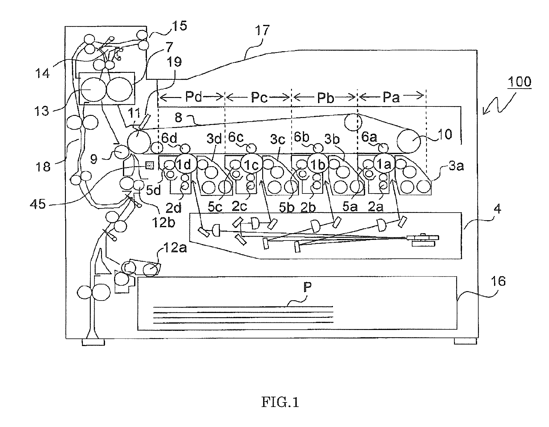
[0033]FIG. 1 is a schematic cross-sectional view illustrating an overall configuration of an image forming apparatus including a developing device according to an embodiment of the present invention. In FIG. 1, a tandem color image forming apparatus is shown as an example of the image forming apparatus. In a main body of a color image forming apparatus 100, four image forming parts Pa, Pb, Pc, and Pd are arranged in order upstream from a conveying direction (i.e., from the right side of FIG. 1). The image forming parts Pa, Pb, Pc, and Pd correspond to images of four different colors (cyan, magenta, yellow, and black), respectively, and sequentially form cyan, magenta, yellow, and black images in the process of charging, exposure, development, and transfer.

[0034]The image forming parts Pa, Pb, Pc, and Pd include photosensitive drums 1a, 1b, 1c, and 1d, respectively, that bear visi...


PUM


Abstract

A developing device includes a developer container storing a developer, a developer supplying member supplying a toner stored in the developer container to an image bearing member, a voltage applying unit capable of applying a bias voltage to the developer supplying member, an image density detecting unit detecting a density of toner formed on the image bearing member, and a control unit correcting a toner concentration in the developer on the basis of a result of image density detection of a reference toner image formed on the image bearing member. The control unit is capable of executing a first toner concentration correction between printing operations and executing a second toner concentration correction between predetermined points during continuous printing.

Description

INCORPORATION BY REFERENCE[0001]This application is based upon and claims the benefit of priority from the corresponding Japanese Patent application No. 2009-108630, filed Apr. 28, 2009, the entire contents of which are incorporated herein by reference.BACKGROUND OF THE INVENTION[0002]1. Field of the Invention[0003]The present invention relates to a developing device included in an image forming apparatus, such as a copier, a facsimile, and a printer, and further relates to an image forming apparatus including the developing device. In particular, the present invention relates to toner concentration control in a developing device that uses a two-component developer containing a magnetic carrier and a toner to develop an electrostatic latent image on an image bearing member.[0004]2. Description of the Related Art[0005]Typical dry-toner developing methods for electrophotographic image forming apparatuses use a one-component developing method or a two-component developing method. The o...

Claims


Application Information

Patent Timeline
Patent Type & Authority Applications(United States)
IPC IPC(8): G03G15/00G03G15/08
CPCG03G15/5041G03G15/0855G03G15/0853
Inventor MABUCHI, SAYO
Owner KYOCERA DOCUMENT SOLUTIONS INC
Why Eureka
Try Eureka