
Toner and method for producing toner

a toner and production method technology, applied in the field of toner and production toner, can solve the problems of achieving both low-temperature fixability and long-term durability, and achieve the effect of reducing image density and deteriorating durability

Active Publication Date: 2020-11-24
CANON KK
View PDF70 Cites 2 Cited by
  • Summary
  • Abstract
  • Description
  • Claims
  • Application Information

AI Technical Summary

Benefits of technology

The present invention provides a toner with the ability to maintain durability and low-temperature fixability on rough paper even after long-term use. This is caused by the strong attachment of an external additive with a large particle diameter to toner particles that contain inorganic fine particles near the surface of the toner particles. The method for producing this toner is also provided.

Problems solved by technology

However, achieving both low-temperature fixability and long-term durability remains a matter for investigation.

Method used

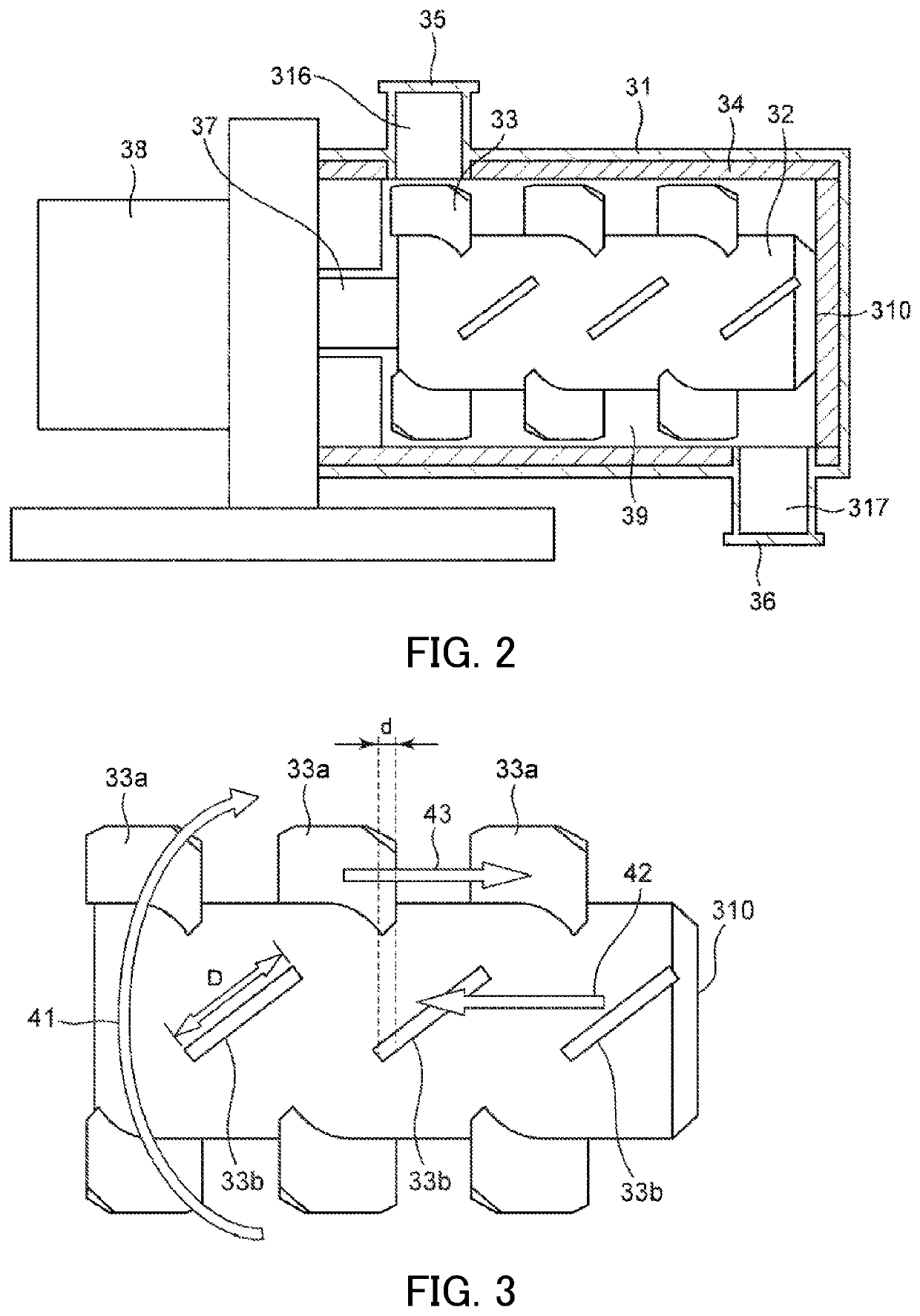

Image

  • Toner and method for producing toner
  • Toner and method for producing toner
  • Toner and method for producing toner

Examples


working example 1

[0585]Toner 1 was filled in a cartridge (CF230X) for a HP printer (LaserJet Pro m203dw) that uses a cleaner-less system, and the following evaluations were carried out. The evaluation results are shown in Table 5.

[0586]

[0587]Image density was evaluated in a high temperature high humidity environment (temperature: 32.5° C., relative humidity: 80%). As a long-term durability test, and with one job being one sheet of a horizontal line pattern having a print percentage of 1%, a total of 7,000 sheets were printed in a mode whereby the machine was temporarily stopped between jobs. Image density was measured for the first print, the 3,000th print and the 7,000th print. A4 color laser photocopying paper (available from Canon, Inc., 80 g / m2) was used. Image density was measured by measuring the reflection density of a solid round image having diameter of 5 mm using an SPI filter with a Macbeth densitometer (available from GretagMacbeth), which is a reflection densitometer. A higher numerical...

working examples 2 to 17

, Comparative Examples 1 to 8

[0597]Evaluations were carried out in the same way as in Working Example 1. The evaluation results are shown in Table 5.

[0598]

TABLE 5Image density(H / H) afterImage density7,000 printsLow-temperatureFoggingTransfer-(H / H)and thenfixability (° C.) (N / N)(° C.) (L / L)abilityFirst3,000th 7,000thleft forFirst3,000th 7,000thFirst3,000th 7,000th(%)printprintprint3 daysprintprintprintprintprintprint(H / H)Example 1Toner 11.481.471.471.452002002000.30.50.690Example 2Toner 21.481.461.431.422052052050.30.30.495Example 3Toner 31.481.461.441.411951951950.40.50.788Example 4Toner 41.471.431.411.352002002050.50.80.892Example 5Toner 51.471.451.441.412002002000.40.70.882Example 6Toner 61.471.421.371.361951952000.50.60.883Example 7Toner 71.461.421.371.351951952000.70.70.882Example 8Toner 81.451.391.351.331951952001.01.31.785Example 9Toner 91.451.381.341.281951952000.60.80.978Example 10Toner 101.481.391.321.301951952000.70.80.982Example 11Toner 111.461.451.431.412052052050.70.70....


PUM

PropertyMeasurementUnit
number average particle diameteraaaaaaaaaa
accelerating voltageaaaaaaaaaa

Abstract

A toner comprising an external additive and a toner particle including a binder resin, a colorant and inorganic fine particles A, wherein the external additive contains an external additive B, a number average particle diameter of primary particles of the external additive B is 30 to 200 nm, an adhesion index of the external additive B to the toner particle is 0.00 to 3.00, a number average particle diameter of primary particles of the inorganic fine particles A is greater than that of the external additive B, and in SEM observations of the toner under specific condition, the number of particles (Na) of the external additive B in a 2 μm square region of the toner surface and the number of particles (Nb) of the external additive B observed in a state of overlapping with the inorganic fine particles A in the region satisfy Nb / Na of 0.20 or more.

Description

BACKGROUND OF THE INVENTIONField of the Invention[0001]The present invention relates to a toner used in an image formation method such as an electrophotography method, and to a method for producing the toner.Description of the Related Art[0002]Demands have been placed on electrophotographic image forming apparatuses in terms higher speeds, longer service lives and lower energy consumption, and there have been demands for significant improvements in various properties of toners in response to these demands. For toners in particular, there have been demands for significant improvements in quality stability, that is, long term durability, from the perspective of extending service life, and there have been demands for significant improvements in low-temperature fixability from the perspectives of increasing speed and lowering energy consumption.[0003]In the past, there were methods for improving long term durability by externally adding large amounts of inorganic fine particles from the...

Claims


Application Information

Patent Timeline
Patent Type & Authority Patents(United States)
IPC IPC(8): G03G9/08G03G9/087G03G9/097
CPCG03G9/08711G03G9/09716G03G9/08755G03G9/0806G03G9/0821G03G9/0819G03G9/083G03G9/09725G03G9/0825G03G9/09733G03G9/0833G03G9/0836G03G9/0838G03G9/0815
Inventor NISHIKAWA, KOJIFUKUDOME, KOSUKEFURUI, TAKAAKIKINUMATSU, TETSUYA
Owner CANON KK
Learn More