Electrophotographic photoreceptor

a photoreceptor and electron microscopy technology, applied in the field of electron microscopy photoreceptors, can solve the problems of easy deformation of the quality of the layer, easy contamination of the surface of the charge transfer layer by foreign matter, and easy contamination of the surface of the charge transfer layer, so as to reduce the sensitivity and reduce the sharpness of the image. , the effect of preventing the defect of the imag

Inactive Publication Date: 2007-02-13
KONICA MINOLTA INC
View PDF5 Cites 3 Cited by
  • Summary
  • Abstract
  • Description
  • Claims
  • Application Information

AI Technical Summary

Benefits of technology

[0013]This invention is proposed to dissolve the foregoing problems. The objective of the invention is to prevent the defects of the image caused by the decrease of the sensitivity, which tends to occur in the course of high speed copying or copying under a low temperature and low humidity condition, by the lowering of the sharpness of the image accompanying the decreasing of image density and thinning of character image caused by the charge fluctuation of the solid black image area. Further objectives of the invention is to provide an electrophotographic photoreceptor, and a processing cartridge, an image forming method and an image forming apparatus each using the photoreceptor, by which recurring image defects such as the black spotting and the lacking of toner transfer caused by the contamination on the photoreceptor surface and the damage such as cracking of the photoreceptor surface are prevented and a clear electrophotographic image of high optical density and high resolution is continuously obtained.
[0014]As a result of the detailed investigation by the inventors on the binder resin and the charge transfer material constituting the charge transfer layer, it was discovered that as the compatibility of the charge transfer material with the binder resin is raised, the high speed response of the sensitivity under low temperature and low humidity is improved, the contamination of the surface of the photoreceptor is inhibited to prevent the occurrence of the recurring image defects such as black spotting and the lack of toner transfer, damage such as the cracking, and a clear image of high density and high resolution can be stably obtained when a mixture of compounds each having different molecular weight from each other is used as the charge transfer material.

Problems solved by technology

However, in the charge transfer layer having such a constitution, the quality of the layer is easily degraded and the surface of the charge transfer layer is also easily contaminated by foreign matter.
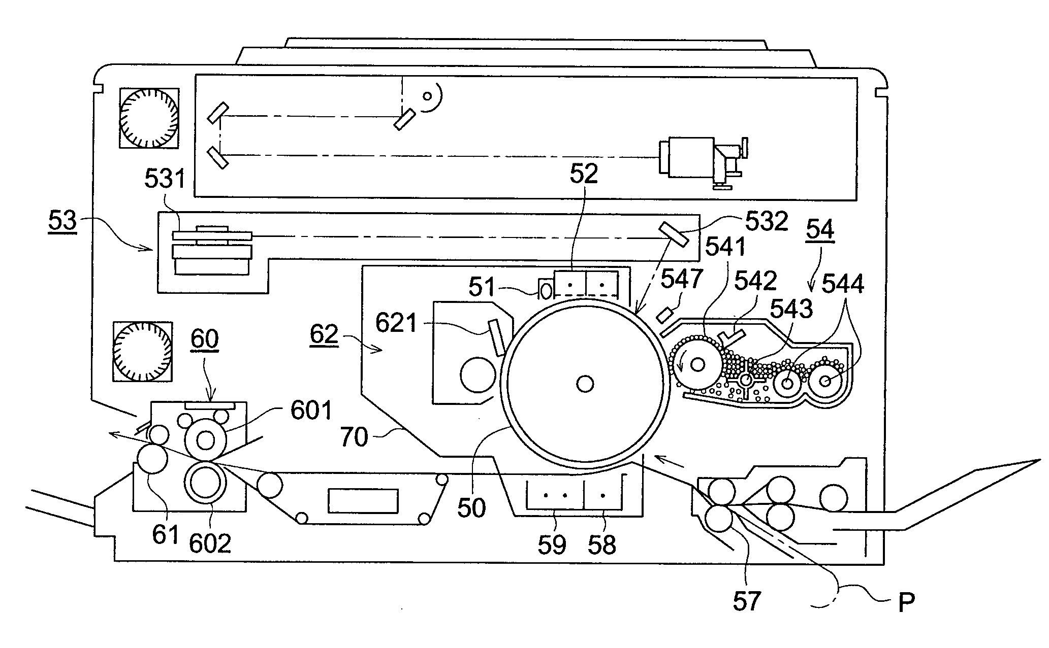
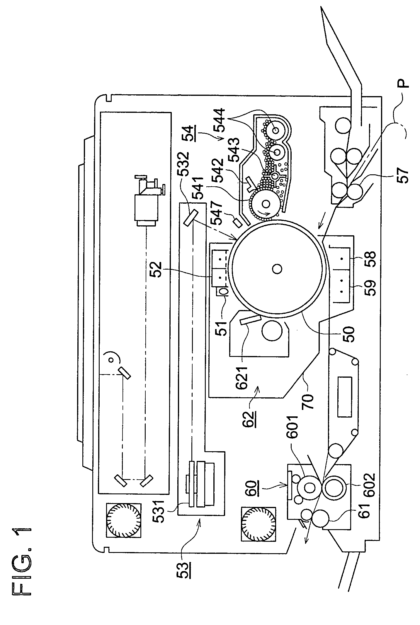
The surface of the photoreceptor tends to be contaminated by paper powder or toner components during the developing process, transferring unit and cleaning unit arranged around the photoreceptor.
As a result of that, recurring image defects such as a black spotting (spots in a strawberry shape) and lacking of toner transfer tends to occur.
Satisfactory sensitivity is difficult to obtain in a high speed copying machine in which the duration between the exposing process and the developing process is very short or under a low temperature and / or low humidity condition.
As a result of that, dot image cannot be exactly reproduced and a fine line image tends to be easily degraded.
Such a compound, however, cannot be uniformly dispersed in the binder resin when the compound is contained in the charge transfer layer since the compatibility of the compound with the binder resin tends to be insufficient.
Consequently, the sensitivity becomes insufficient and damage such as cracking of the charge transfer layer tends to occur.
However, the residual potential tends to be raised on the photoreceptor using such the compound since the terminal of the compound is not blocked and the problem of the compatibility with the binder resin has not been sufficiently dissolved.
However the use of the fluororesin particles in the surface layer tends to cause the image spreading.
The mechanical strength of the surface layer also tends to be degraded and the surface of the photoreceptor is easily worn by the friction of the cleaning unit.
Accordingly, a satisfactory image cannot be constantly provided.

Method used


Image

  • Electrophotographic photoreceptor
  • Electrophotographic photoreceptor
  • Electrophotographic photoreceptor

Examples


example 4

SYNTHESIZING EXAMPLE 4

Synthesis of Compound 12B (m=0)

[0114]

[0115]Into a 100 ml four-mouth flask to which a nitrogen gas inlet pipe, a cooler, a thermometer and a stirrer were equipped, 1.96 g (0.075 moles) of potassium tert-butoxide 4 and 20 ml of tetrahydrofuran, hereinafter referred to as THF, were charged and stirred while introducing nitrogen gas.

[0116]A solution was prepared by dissolving 1.0 g (0.003 moles) of Compound 1 and 2.63 g (0.007 moles) of Compound 2 and 2.25 g (0.008 moles) of Compound 3 dissolved in 20 ml of THF. The solution was gradually dripped into the mixture of potassium tert-butoxide 4 and THF while the temperature was maintained at 45° C. After the finish of the dripping, reaction was carried out for 5 hours while maintaining a temperature of from 45 to 50° C.

[0117]To another 200 ml beaker, a stirrer was equipped and 20 ml of methanol was charged and stirred. The reaction liquid after the reaction for 5 hours was poured to the methanol, and 20 ml of water wa...

example 5

SYNTHESIZING EXAMPLE 5

Synthesis of Compound 11B (m=0)

[0121]

[0122]Into a 100 ml four-mouth flask to which a nitrogen gas inlet pipe, a cooler, a thermometer and a stirrer were equipped, 1.96 g (0.075 moles) of potassium tert-butoxide 4 and 20 ml of tetrahydrofuran, hereinafter referred to as THF, were charged and stirred while introducing nitrogen gas.

[0123]A solution was prepared by dissolving 1.0 g (0.003 moles) of Compound 1 and 2.46 g (0.007 moles) of Compound 2 and 2.41 g (0.008 moles) of Compound 3 dissolved in 20 ml of THF. The solution was gradually dripped into the mixture of potassium tert-butoxide 4 and THF while the temperature was maintained at 45° C. After the finish of the dripping, reaction was carried out for 5 hours while maintaining a temperature of from 45° C. to 50° C.

[0124]To another 200 ml beaker, a stirrer was equipped and 20 ml of methanol was charged and stirred. The reaction liquid after the reaction for 5 hours was poured to the methanol, and 20 ml of wate...

example 6

SYNTHESIZING EXAMPLE 6

Synthesize of Compound 17C

[0136]Into a 100 ml four-mouth flask to which a nitrogen gas inlet pipe, a cooler, a thermometer and a stirrer were equipped, 4.08 g (0.04 moles) of 2,4-dimethylaniline, 4.08 g (0.02 moles) of iodobenzene, 9.9 g (0.03 moles) of di-iodobenzene, 1.27 g (0.02 moles) of powdered copper and 11.04 g (0.08 moles) of potassium carbonate were charged and reacted over 30 hours at 190° C. while introducing nitrogen gas.

[0137]The reaction liquid was cooled to 60° C. and 200 ml of THF was added to the liquid, and the mixture was filtered. The filtrate was concentrated and dissolved in 100 ml of toluene and 10 g of Wakogel B-0 (Wako Pure Chemical Industries, Ltd.) was added, and stirred for 30 minutes and filtered. Filtered Wakogel was washed by 30 ml of toluene. The filtrate and the washing liquid were concentrated and dried. The dried substance was dissolved in 20 ml of THF and the solution was dripped into 120 ml of methanol for purifying by re-p...


PUM


Abstract

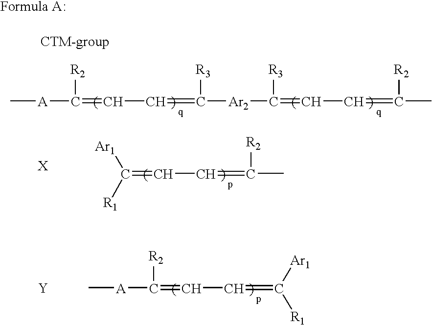
An electrophotographic photoreceptor comprising a support and a photosensitive layer is disclosed. The photosensitive layer contains a mixture of compounds represented by Formula (1) having different n and (Rp+Rs) is not more than 99%, wherein Rp is a ratio of a component having the maximum content in the mixture and Rs is a ratio of a component having the content next to the maximum content in percent.X—(CTM-group)n—Y  (1)In the formula, CTM-group is a charge transfer group; X and Y are each a hydrogen atom, a halogen atom or a mono-valent organic group; and n is an integer of from 0 to 10, provided that n is an integer of from 1 to 10 when both X and Y are hydrogen atom or a halogen atom. A processing cartridge comprising the electrophotographic photoreceptor is also disclosed.

Description

FIELD OF THE INVENTION[0001]The present invention relates to an electrophotographic photoreceptor, a processing cartridge, an image forming apparatus and an image forming method to be used for image formation by the electrophotographic process, further in detail, relates to the electrophotographic photoreceptor, processing cartridge, image forming apparatus and image forming method to be used for image formation by the electrophotographic process commonly used in the field of copying machine and printer.BACKGROUND OF THE INVENTION[0002]Recently, organic photoreceptor has become the principal type of electrophotographic photoreceptors in place of an inorganic photoreceptor. The reason being that organic photoreceptor has a wider selection range of a photosensitive material, superiority in environmental suitability and lower cost compared with an inorganic photoreceptor such as a selenium photoreceptor and an amorphous silicon photoreceptor.[0003]Besides, digital image forming system ...

Claims


Application Information

Patent Timeline
Patent Type & Authority Patents(United States)
IPC IPC(8): G03G15/02G03G5/06G03G5/07G03G9/09G03G9/097
CPCG03G5/0666G03G5/0672G03G9/091G03G9/09783G03G5/06144G03G5/061443G03G5/061473
Inventor SAKIMURA, TOMOKOSHIBATA, TOYOKO
Owner KONICA MINOLTA INC
Why Eureka
Try Eureka