Eureka AIR delivers breakthrough ideas for toughest innovation challenges, trusted by R&D personnel around the world.

Image forming apparatus, image forming method, and process cartridge

a technology of image forming and process cartridge, which is applied in the direction of electrographic process apparatus, instruments, optics, etc., can solve the problems of image degradation, image loss, image degradation, etc., and achieve the effect of reducing image density, stably forming, and suppressing image degradation

Inactive Publication Date: 2010-06-01
RICOH KK
View PDF22 Cites 3 Cited by
  • Summary
  • Abstract
  • Description
  • Claims
  • Application Information

AI Technical Summary

Benefits of technology

[0015]The present invention is proposed in view of the present situation and aims to overcome the various conventional problems and to achieve the following objects. It is an object of the present invention to provide an image forming apparatus and a cartridge, which have high-durability and are enabled to suppress image degradation caused by a reduction in image density upon repetitive use when the concentration of discharge products becomes uneven on the surface of an electrophotographic photoconductor in the vicinity of a corona discharging type charging unit (a discharge region of an image forming area of the charging unit) which discharges in a non-contact manner. Therefore, the image forming apparatus and the process cartridge are enabled to stably form a high quality image without image blur, image deletion or unevenness of the halftone image density even when repetitively used for long hours. It is also an object of the present invention to provide an image forming method employed by the image forming apparatus and the cartridge.

Problems solved by technology

However, there are problems that this causes an increase in residual potential on the photoconductor and image degradation such as image blur.
Therefore, it may cause image deletion, image blur, or the like.

Method used


Image

  • Image forming apparatus, image forming method, and process cartridge
  • Image forming apparatus, image forming method, and process cartridge
  • Image forming apparatus, image forming method, and process cartridge

Examples


production example 1

Preparation of Electrophotographic Photoconductor 1

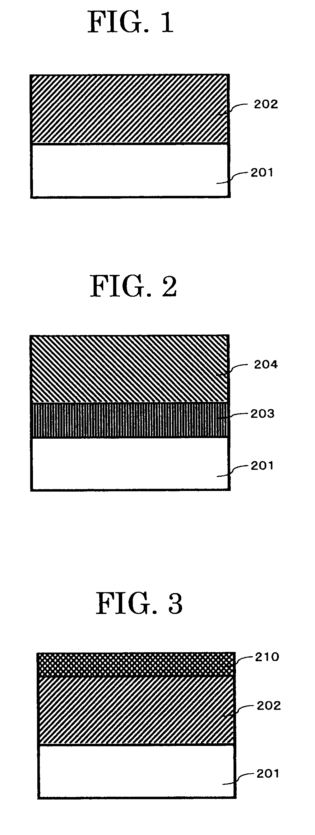
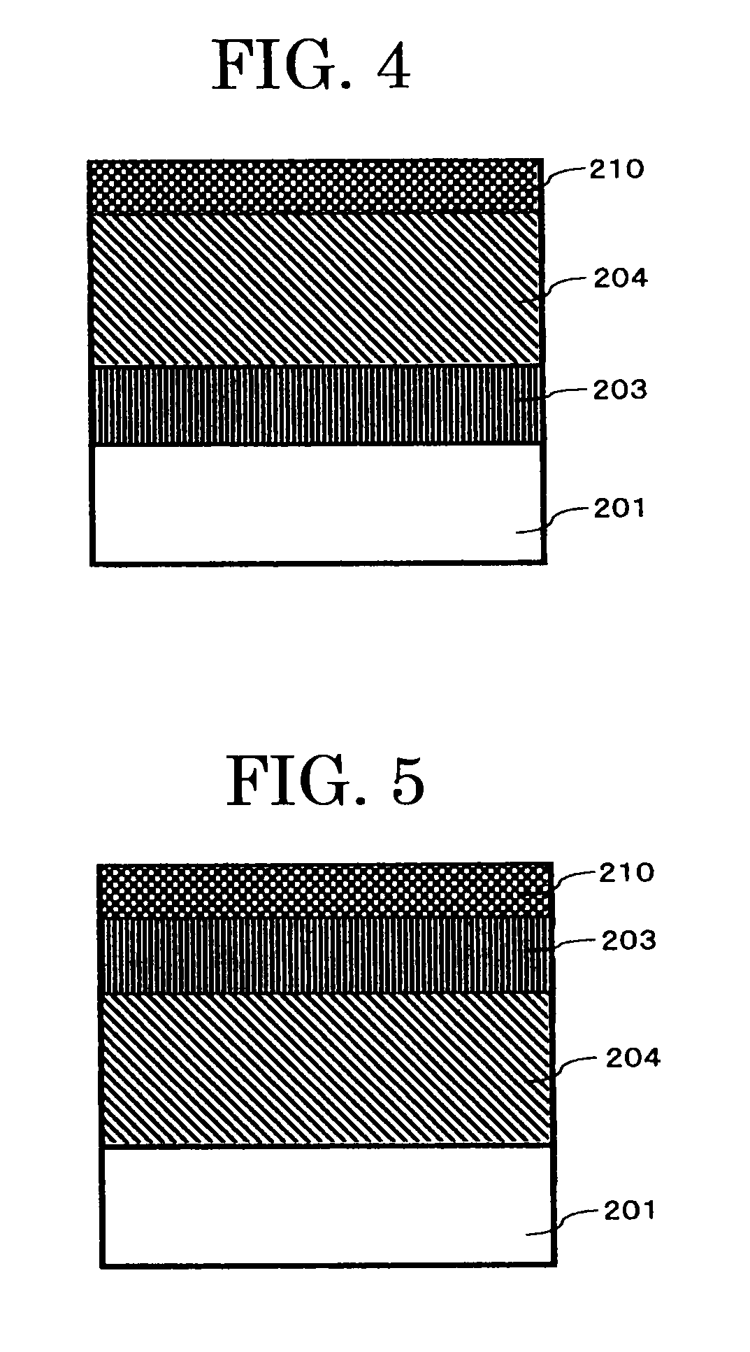
[0341]Over the surface of an aluminum cylinder, an undercoat layer coating solution, a charge generating layer coating solution and a charge transporting layer coating solution each having the following composition were applied in this order by immersion coating, the applied coating solutions were respectively dried to thereby form an undercoat layer having a thickness of 3.5 μm, a charge generating layer having a thickness of 0.2 μm and a charge transporting layer having a thickness of 22 μm, respectively.

[0342]

Titanium dioxide powder400 parts by massMelamine resin 65 parts by massAlkyd resin120 parts by mass2-butanone400 parts by mass

[0343]Bisazo pigment represented by the following structural formula . . . 12 parts by mass

[0344][0345]Polyvinyl butyral . . . 5 parts by mass[0346]2-butanone . . . 200 parts by mass[0347]Cyclohexanone . . . 400 parts by mass

[0348]Polycarbonate (Z POLICA, manufactured by Teijin Chemicals, Ltd.) . . . ...

production example 2

Preparation of Electrophotographic Photoconductor 2

[0362]An electrophotographic photoconductor 2 was prepared in the same manner as in Production Example 1 except that the protective coating solution was changed to a protective coating solution having the following composition.

[0363]Alumina filler (average primary particle diameter: 0.3 μm, SUMICORANDOM AA-03, manufactured by Sumitomo Chemical Co., Ltd.) . . . 2 parts by mass[0364]Unsaturated polycarboxylic polymer solution (acidic value: 180 mgKOH / g, solid content: 50% by mass, BYK-P104 manufactured by BYK Chemie Co.) . . . 0.02 parts by mass[0365]Exemplified Compound 2 represented by the following structural formula . . . 1.8 parts by mass

[0366][0367]Charge transporting material represented by the following structural formula . . . 1.8 parts by mass

[0368][0369]Polycarbonate (Z POLICA, manufactured by Teijin Chemicals, Ltd.) . . . 5 parts by mass[0370]Tetrahydrofuran . . . 250 parts by mass[0371]Cyclohexanone . . . 70 parts by mass...

production example 3

Preparation of Electrophotographic Photoconductor 3

[0372]An electrophotographic photoconductor 3 was prepared in the same manner as in Production Example 1 except that the protective layer coating solution was changed to a protective layer coating solution having the following composition.

[0373]Alumina filler (average primary particle diameter: 0.3 μm, SUMICORANDOM AA-03, manufactured by Sumitomo Chemical Co., Ltd.) . . . 1 part by mass[0374]Unsaturated polycarboxylic polymer solution (acidic value: 180 mgKOH / g, solid content: 50% by mass, BYK-P104 manufactured by BYK Chemie Co.) . . . 0.01 parts by mass[0375]Exemplified Compound 9 represented by the following structural formula . . . 0.6 parts by mass

[0376][0377]Charge generating material represented by the following structural formula . . . 3 parts by mass

[0378][0379]Polycarbonate (Z POLICA, manufactured by Teijin Chemicals, Ltd.) . . . 5 parts by mass[0380]Tetrahydrofuran . . . 250 parts by mass[0381]Cyclohexanone . . . 70 parts ...


PUM


Abstract

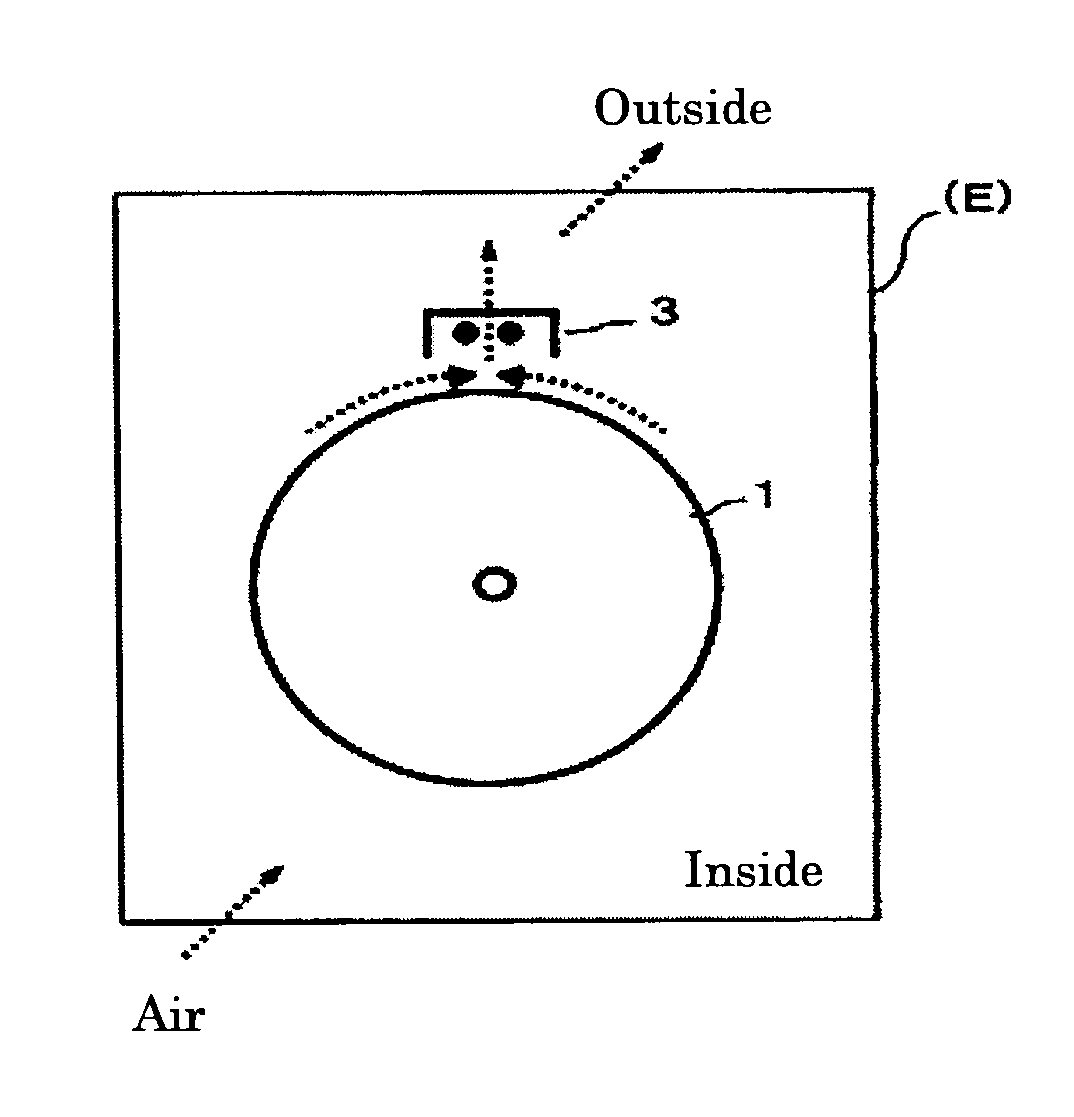
An image forming apparatus and a process cartridge have high-durability and stably form high quality images under long-term use without reducing image density even when concentration of discharge products at the surface of an electrophotographic photoconductor becomes uneven in a discharge region of a charging unit. The apparatus employs an image forming method and has a corona discharge type charging unit discharging in a non-contact manner, the photoconductor placed to face the charging unit and the outermost surface layer thereof contains a filler and an amine compound with a specific structure, and an airflow adjusting device which carries air taken from the outside of the apparatus to the vicinity of the charging unit or the photoconductor so that ozone concentration and unevenness thereof are maintained at an average of 30 ppm or less and 15 ppm or less respectively at the surface of the photoconductor in the discharge region.

Description

BACKGROUND OF THE INVENTION[0001]1. Field of the Invention[0002]The present invention relates to an image forming apparatus, an image forming method and a process cartridge, which achieve high durability and high-quality image.[0003]2. Description of the Related Art[0004]Recent developments in information processing systems using an electrophotographic process are remarkable. In particular, laser printers and digital copiers that record information with a laser beam by converting information into digital signals have been remarkably improved in terms of their print quality and reliability. These laser printers and digital copiers have been combined with high-speed technologies. As a result, they have become used as laser printers and digital copiers capable of full-color printing. With the above-mentioned background, as required functions for an electrophotographic photoconductor (hereinafter, may be referred to as “photoconductor”), it is particularly important to satisfy both high...

Claims


Application Information

Patent Timeline
Patent Type & Authority Patents(United States)
IPC IPC(8): G03G21/20
CPCG03G21/206G03G2215/00957G03G2221/183
Inventor NAKAMORI, HIDEOGONDOH, MASANOBUNOHSHO, SHINJI
Owner RICOH KK
Why Eureka
Eureka Blog
Learn More