Image encoding apparatus and method of controlling same

a technology of image data and encoding apparatus, applied in electrical apparatus, digital video signal modification, pictoral communication, etc., can solve the problems of image degradation, loss of continuity of tiles in images, and noise at tile boundaries,

Active Publication Date: 2018-06-19
CANON KK
View PDF12 Cites 1 Cited by
  • Summary
  • Abstract
  • Description
  • Claims
  • Application Information

AI Technical Summary

Benefits of technology

[0009]The present invention is something conceived in view of these points, and provides a technique that enables maintaining continuity of tiles upon tile division, and achieving an amount of encoded data generated that is much less than that of D2.
[0011]According to the present invention, it is possible to suppress image degradation of a tile boundary while suppressing an increase of an amount of encoded data due to tile division.

Problems solved by technology

This difference means that continuity is lost for tiles in an image obtained by decoding, and consequently noise occurs at tile boundaries.
However, the larger a quantization step is the larger that image degradation becomes.

Method used


Image

  • Image encoding apparatus and method of controlling same
  • Image encoding apparatus and method of controlling same
  • Image encoding apparatus and method of controlling same

Examples


first embodiment

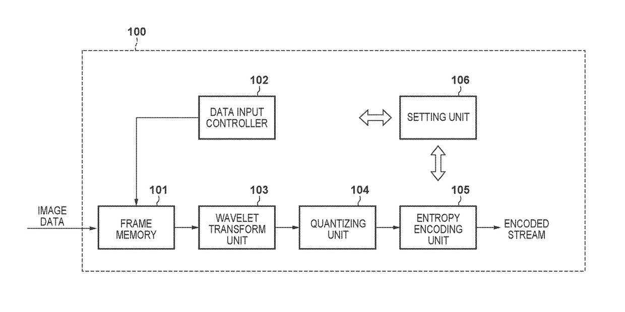
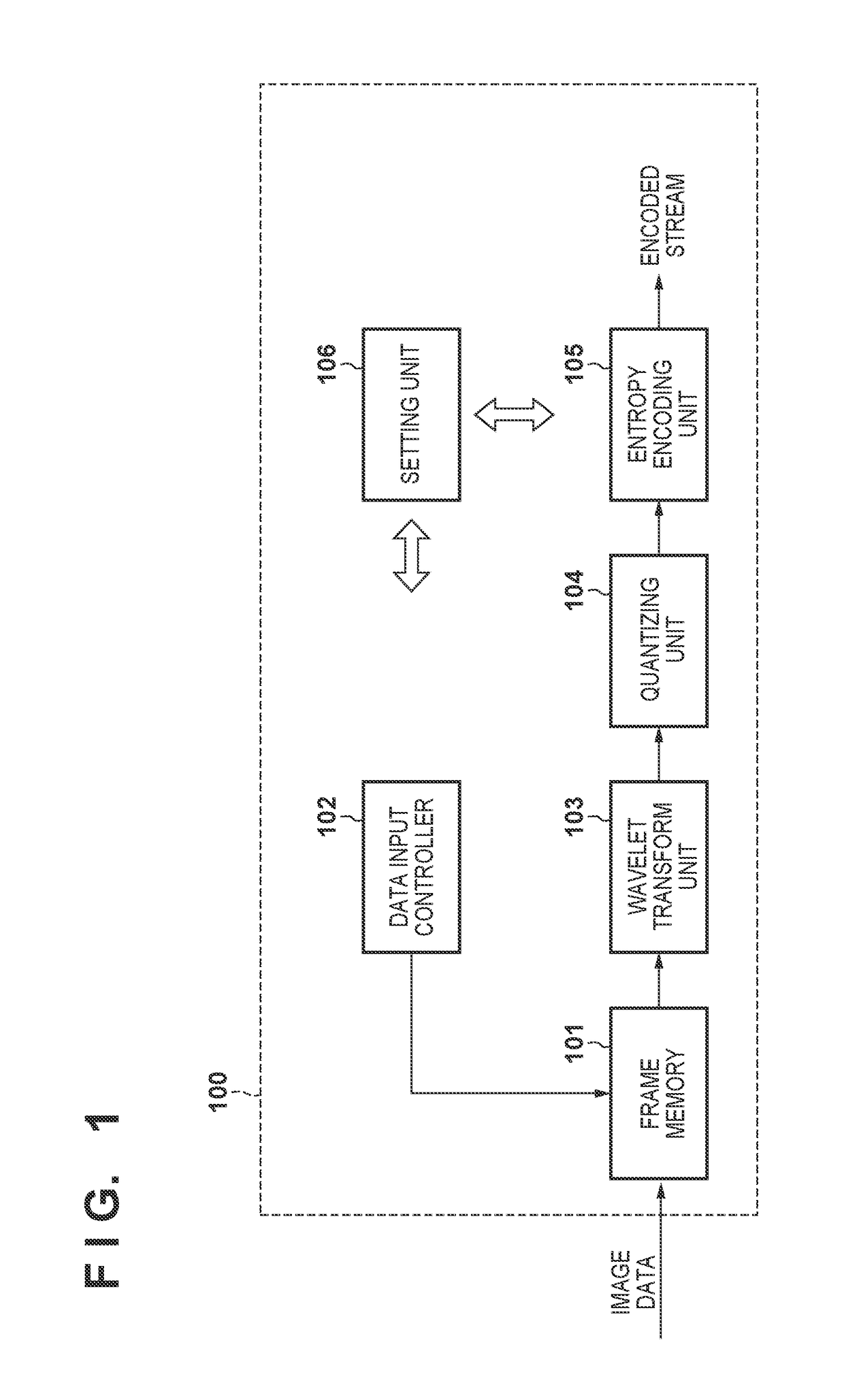
[0025]Explanation is given of an example in which the first embodiment is applied to an image capturing apparatus such as a digital camera. FIG. 1 is a block configuration diagram of an image encoding unit 100 in an image capturing apparatus.

[0026]As shown in the figure, the image encoding unit 100 has a frame memory 101, a data input controller 102, a wavelet transform unit 103, a quantizing unit 104, an entropy encoding unit 105, and a setting unit 106. Note that, in the first embodiment, although explanation is given of an example of using JPEG 2000 as an example of an encoding scheme, the encoding scheme is not particularly questioned. Explanation is given below of a processing procedure for encoding processing based on the configuration of FIG. 1. Here, the setting unit 106 decides, in accordance with an instruction from an operation unit (not shown), how many tiles to divide image data that is an encoding target into, and furthermore how many times to perform a wavelet transfo...

second embodiment

[0109]FIG. 8 depicts a block configuration diagram of an image encoding unit 800 in a second embodiment. The image encoding unit 800 in the second embodiment differs in a point of providing a setting unit 801 instead of the setting unit 106 of FIG. 1 in the first embodiment, and a point of having an encoded data amount adjustment unit 802. In addition, operation of the data input controller 102 and the wavelet transform unit 103 also differs from that for FIG. 1. Note that, in addition to the function of the setting unit 106 of FIG. 1, the setting unit 801 in the second embodiment inputs a compression rate in accordance with an instruction from an operation unit (not shown), and in accordance with this controls the data input controller 102 and the encoded data amount adjustment unit 802. FIG. 9 is a flowchart illustrating a processing procedure in the second embodiment. Below, the processing of each configuration element of FIG. 8 is explained in accordance with the flowchart of FI...


PUM


Abstract

To suppress image degradation of a tile boundary while suppressing an increase of an amount of encoded data due to tile division. When performing a wavelet transform on a tile of interest, a wavelet transform unit performs a wavelet transform by referring to pixel data of the tile of interest and a neighboring tile that neighbors the tile of interest to obtain transformation coefficient data of a set resolution level. From transformation coefficient data obtained from the neighboring tile, the wavelet transform unit supplies a subsequent quantizing unit with transformation coefficient data of each resolution level that is closest to a boundary between the tile of interest and the neighboring tile, as well as all transformation coefficient data obtained from the tile of interest.

Description

BACKGROUND OF THE INVENTION[0001]Field of the Invention[0002]The present invention relates to an encoding technique for image data.[0003]Description of the Related Art[0004]In recent years, various compression encoding methods for image data have been examined in conjunction with the development of digital image capturing apparatuses such as digital cameras and digital video cameras.[0005]JPEG (Joint Photograph Experts Group) 2000 is given as a representative compression encoding method. In JPEG 2000, an image that is an encoding target is divided into at least one or more tiles. A wavelet transform, quantization, and entropy encoding are performed with a tile as one unit. A lossless 5 / 3 tap filter, for example, is used in a wavelet transform. In this filter, one high-pass coefficient is generated from three consecutive pixels, and one low-pass coefficient is generated from five consecutive pixels. Consequently, when subjecting pixels at a boundary of the tile to filter processing, ...

Claims


Application Information

Patent Timeline
Patent Type & Authority Patents(United States)
IPC IPC(8): H04N19/00H04N19/176H04N19/63H04N19/18H04N19/182H04N19/115
CPCH04N19/63H04N19/115H04N19/176H04N19/18H04N19/182H04N19/132
Inventor SAKAMOTO, DAISUKE
Owner CANON KK
Why Eureka
Try Eureka