Electrically controlled pneumatic end of train pneumatic emulation system

a technology of electric control and pneumatic emulation system, which is applied in the direction of braking system, instruments, analogue processes for specific applications, etc., can solve the problems of reduced braking efficiency of the train, inability to achieve graduated release, and extra costs associated with i

Inactive Publication Date: 2005-01-04
WABTEC HLDG CORP
View PDF7 Cites 36 Cited by
  • Summary
  • Abstract
  • Description
  • Claims
  • Application Information

AI Technical Summary

Benefits of technology

The ECP / HOT interface unit includes software modified EOT which acts as the ECP Head End Unit (HEU) to the remaining train cars of the train consist and which provides brake commands in response to changes in the brake pipe pressure. Individual ECP equipped cars may respond primarily to the data messages over the ECP trainline as initiated from the ECP / HOT interface unit. However, the ECP equipped cars may also apply and release the brake applications in response to changes in brake pipe pressure in a manner similar to conventional pneumatic brake valves when there is a failure to receive the ECP message. This feature thus allows ECP equipped train cars to operate with conventionally equipped pneumatic brakes so long as the ECP trainline maintains train electrical continuity. Thus, the systems of the present invention may be implemented using a mixed fleet of ECP and non-ECP equipped trains.

Problems solved by technology

Another problem of conventional brake systems using pneumatic control system is slow propagation rates of the compressed air along the brake pipe which reduces the braking efficiency of the train as well as the inability for graduated release.
This is primarily driven by the extra costs associated with the need to support both pneumatic and ECP brake application systems on each train car of the train consist.
However, implementation of ECP systems on major Class 1 railroads is more challenging due to the difficulty in dedicating locomotives for ECP operation prior to equipping the entire fleet.
A drawback to ECP systems is the cost of implementing the equipment for an entire fleet such as, for example, retrofitting the locomotive with control units and transceivers and each car with sensors, control valves and the like.
Moreover, the standalone ECP systems, without emulation capability, still need to have a level of “limp home” capability to accommodate cases where the only available locomotives are not ECP equipped, or there is an in-route failure of the ECP head-end-unit (HEU) hardware.
Unfortunately, without having quick service and release capabilities, the ability to emulate pneumatic brake operation is quite limited, and would result in severe speed restrictions probably in the area of 20 mph.
This would not be acceptable for planned operation with non-ECP equipped locomotives for any significant distances.

Method used


Image

  • Electrically controlled pneumatic end of train pneumatic emulation system
  • Electrically controlled pneumatic end of train pneumatic emulation system
  • Electrically controlled pneumatic end of train pneumatic emulation system

Examples


Embodiment Construction

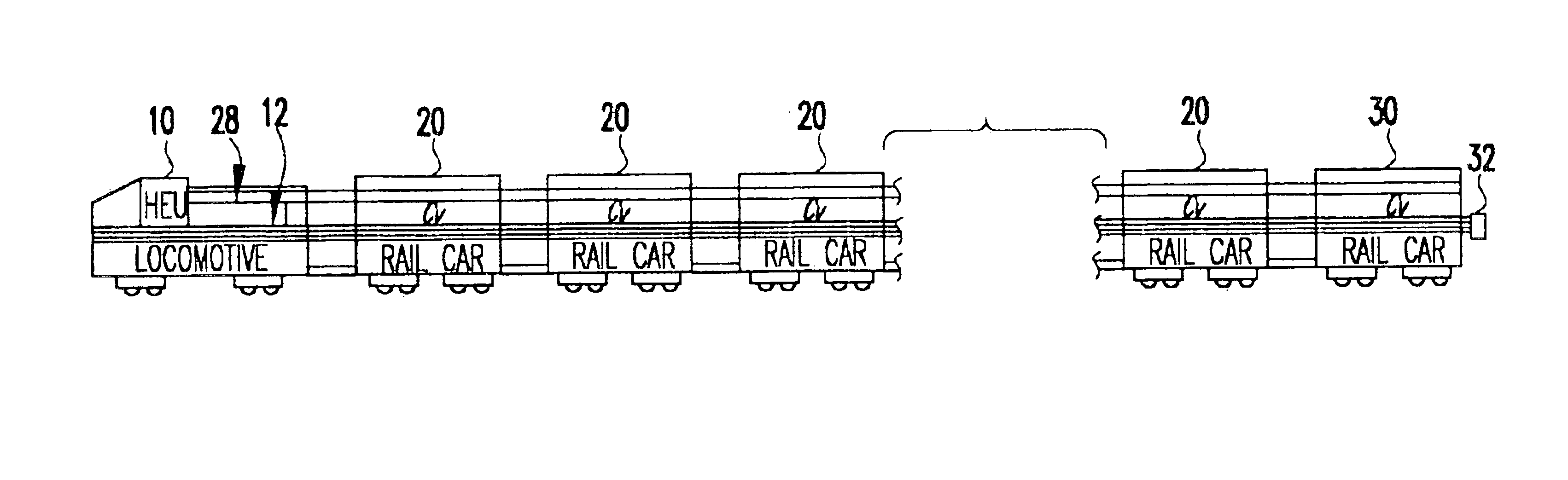
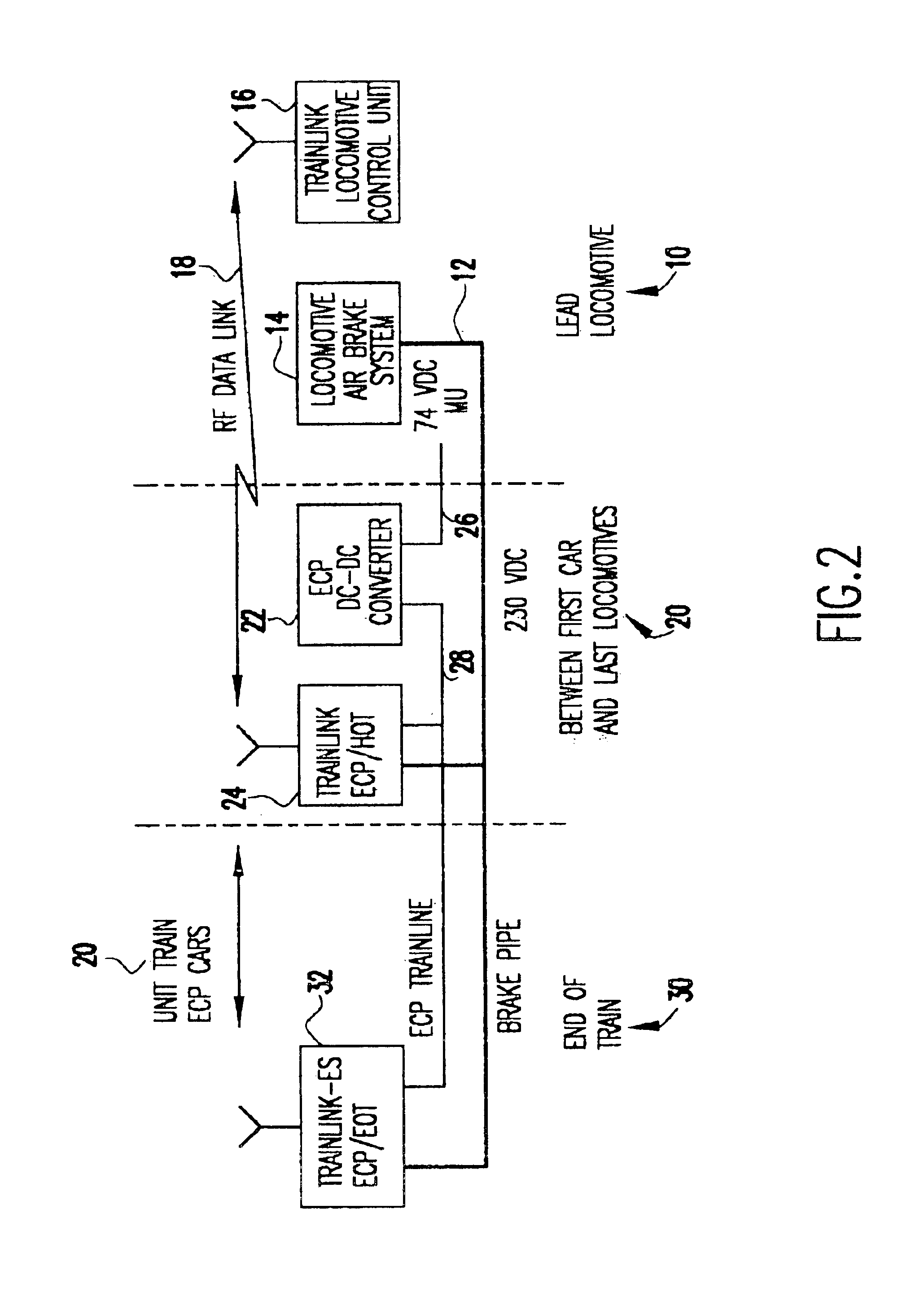
The present invention generally relates to intra-train communications for implementing Electrically Controlled Pneumatic (ECP) railroad freight train brakes on a train car. More specifically, the present invention allows full train speed operation of standalone ECP unit trains, even with non-ECP equipped locomotives. The system of the present invention is based upon a close operational integration with the end of train (EOT) system and preferably maintains full brake pipe continuity and normal pneumatic emergency functions throughout each train car of the train consist.

One of the primary advantages of using the system of the present invention is that the same pneumatic gages or screen indicators used for conventional pneumatics operation as the main feedback of braking action on lead locomotives may be used with the system of the present invention. In this way, a lead locomotive does not have to be retrofitted for ECP operations. Also, unlike conventional systems, the train brake ap...


PUM


Abstract

An electronically controlled pneumatic (ECP) end of train (EOT) pneumatic emulation system allows fill train operation of standalone ECP unit trains, even with non-ECP equipped locomotives. The emulation system is based on close integration with the EOT system and allows operation of unit trains equipped with “all electric” ECP without pneumatic overlay or emulation capability, using standard, non-ECP equipped locomotives.

Description

BACKGROUND OF THE INVENTION1. Field of the InventionThe present invention generally relates to an electronically controlled pneumatic (ECP) end of train (EOT) pneumatic emulation system and, more particularly, to a pneumatic emulation system which allows full train speed operation of standalone ECP train units with non-ECP equipped locomotives.2. Background DescriptionAir brakes are the most commonly used brakes for freight trains. These brakes use changes compressed air pressure to control the operation of the brakes at each car along the train. A “brake pipe” connects all of the cars in the train and the locomotives, with the locomotives supplying the pressurized air to the brake pipe. The brake pipe may extend upwards of one mile or longer and provide the necessary air pressure to the brakes of each car of the train for braking operations.In the most typical brake application systems, the brake control is actuated from a “driver's brake valve”. The driver's brake valve allows air...

Claims


Application Information

Patent Timeline
Patent Type & Authority Patents(United States)
IPC IPC(8): B60T13/66B60T13/26
CPCB60T13/665
Inventor KULL, ROBERT C.
Owner WABTEC HLDG CORP
Why Eureka
Try Eureka