Eureka AIR delivers breakthrough ideas for toughest innovation challenges, trusted by R&D personnel around the world.

Method and apparatus for allocating frequency resources in a wireless communication system supporting frequency division multiplexing

requency division multiplexing technology, applied in the field of resource allocation in a wireless communication system, can solve the problems of inconvenient real-time traffic, inability to adapt to the traffic of frequency diversity technology, and inability to meet the traffic needs of real-time traffic, so as to prevent collision

Inactive Publication Date: 2008-01-10
SAMSUNG ELECTRONICS CO LTD
View PDF7 Cites 36 Cited by
  • Summary
  • Abstract
  • Description
  • Claims
  • Application Information

AI Technical Summary

Benefits of technology

The present invention provides a method for allocating frequency resources in a wireless communication system that ensures stable frequency diversity and prevents collisions between terminals. The method includes hierarchizing resource units, dividing them into blocks, and allocating them as frequency resources for each terminal. The blocks can be different in size and can be allocated to different terminals. The method also includes performing hierarchical hopping of the allocated blocks to ensure continuous frequency resources for each terminal. The technical effects of the invention include stable frequency diversity, prevention of collisions, and efficient allocation of frequency resources.

Problems solved by technology

Generally, in wireless communication system, the channel environment is subject to change not only due to Additive White Gaussian Noise (AWGN), but also due to a power variation of a received signal, caused by fading, shadowing, a Doppler effect based on movement and frequent velocity change of terminals, interference by other users or multipath signals, and the like.
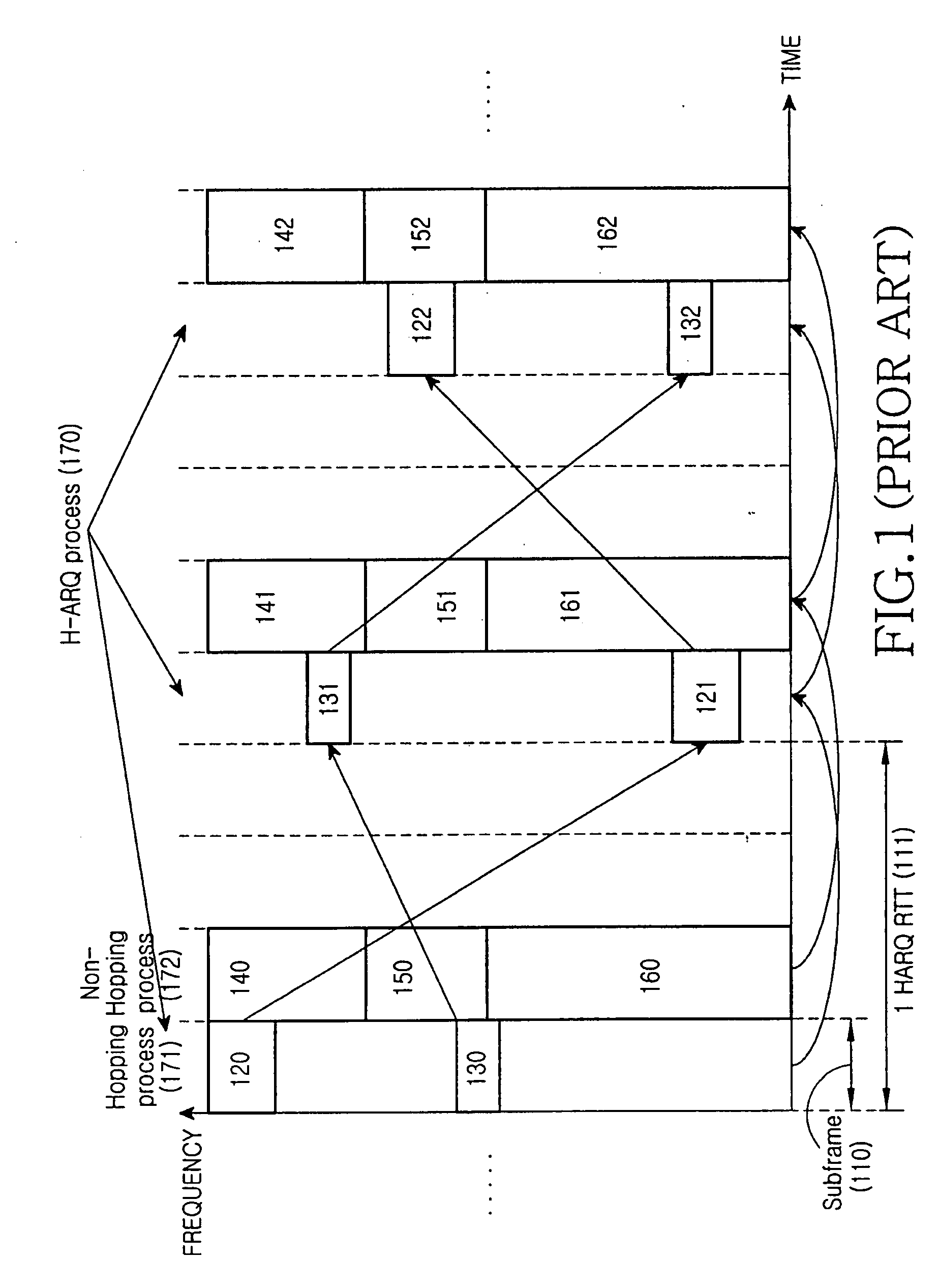
The frequency diversity technology is not suitable for the traffic, such as a broadcast channel or a common control channel, which should not be particularly applied to the channel environment of a specific user, and for the traffic, such as the real-time traffic, which are susceptible to delay.
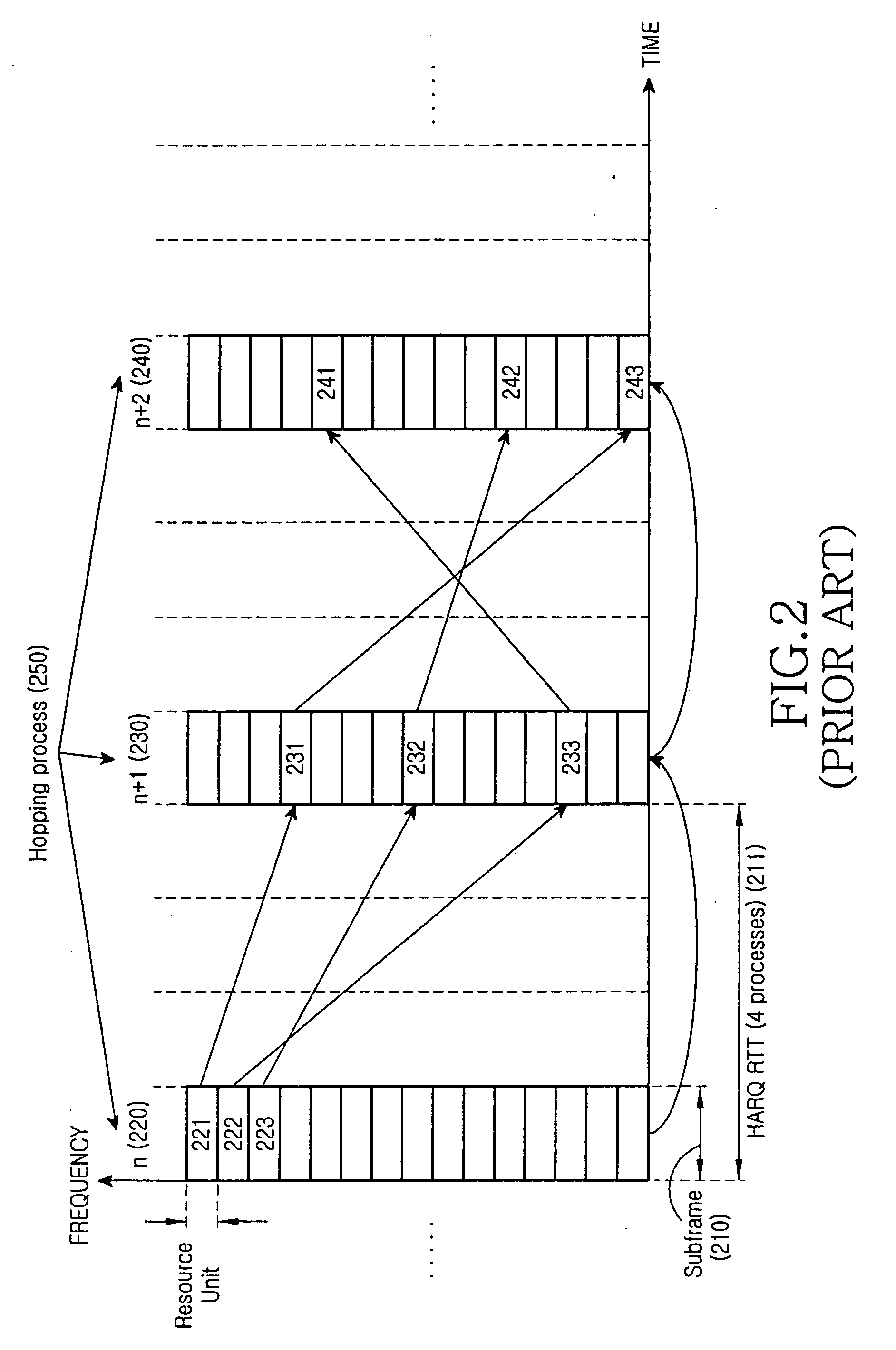
Therefore, it is not possible to employ the pattern in which hopping happens independently for each individual RU as described in FIG. 2.

Method used


Image

  • Method and apparatus for allocating frequency resources in a wireless communication system supporting frequency division multiplexing
  • Method and apparatus for allocating frequency resources in a wireless communication system supporting frequency division multiplexing
  • Method and apparatus for allocating frequency resources in a wireless communication system supporting frequency division multiplexing

Examples


embodiment 1

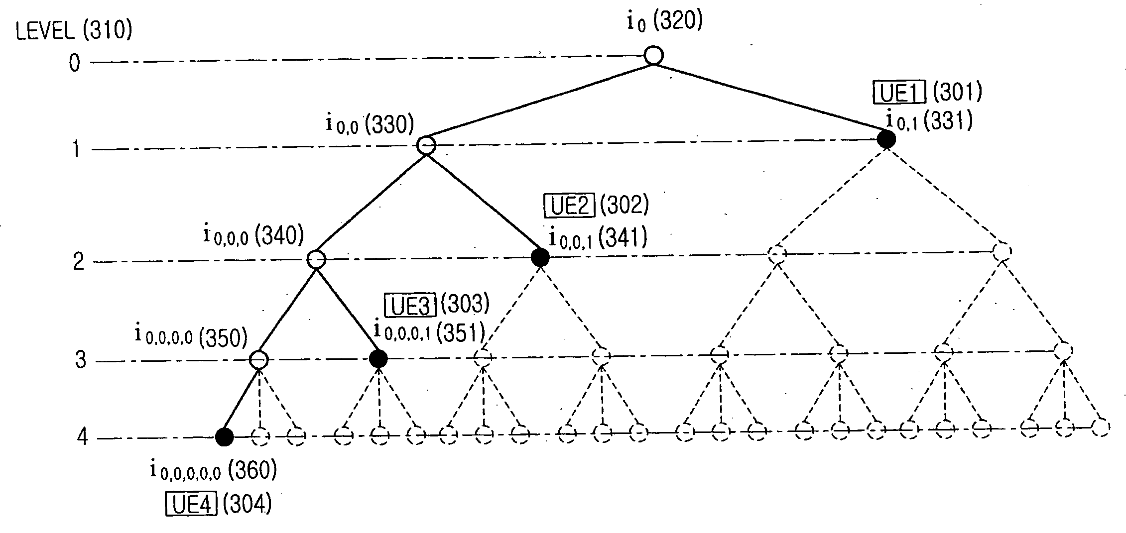
[0096]FIG. 3A illustrates a node tree structure for frequency resource allocation in a wireless communication system according to Embodiment 1 of the present invention.

[0097] Assume that a basic unit of frequency resource allocation is an RU formed of a set of consecutive sub-carriers in a frequency band, and upper / lower positions of nodes in the tree structure of FIG. 3A are defined as levels 0-4 LEVEL 310. In FIG. 3A, when nodes belonging to the lowermost level 4 are identical to the basic frequency resource RU in the 5-level node tree, 8 nodes i0,0,0,0, i0,0,0,1, i0,0,1,0, i0,0,1,1, i0,1,0,0, i0,1,0,1, i0,1,1,0, and i0,1,1,1 belonging to the level 3 each correspond to 3 consecutive RUs; 4 nodes i0,0,0, i0,0,1, i0,1,0, and i0,1,1 belonging to the level 2 each correspond to 6 consecutive RUs; 2 nodes i0,0, and i0,1 belonging to the level 1 each correspond to 12 consecutive RUs; and finally, a node i0 in the uppermost level 0 corresponds to 24 consecutive RUs, which are resources o...

embodiment 2

[0115]FIG. 5 illustrates a node tree structure for frequency resource allocation in a wireless communication system according to Embodiment 2 of the present invention.

[0116] Referring to FIG. 5, definitions will be given of general formulae for frequency allocation at an arbitrary time when the system allocates resources in a manner of the faired node tree and transmits data by hopping an allocated frequency band according to a given hopping pattern. As shown in FIG. 5, LEVEL 510 of the node tree are defined as levels 0 to L, the number of nodes belonging to nodes of the same upper level in an lth level (where l is an integer between 0 and L) is defined as Nl, and the number of RUs belonging to one node in an lth level is defined as Rl. According to the definition of the faired node tree, Nl and Rl are identical in the nodes belonging to a particular level, and for Embodiment 1, the Nl and Rl values in each level can be defined as Equation (6).

N0=1, N1=2, N2=2, N3=2, N4=3,

R0=24, ...

embodiment 3

[0122] Embodiment 1 or Embodiment 2, assuming the faired node tree, has independently defined {Sl,nl-1,nl}, nl=0, . . . , Nl-1 for each individual level, or according to an upper node belonging to the same level. Embodiment 3, a special case of Embodiment 1 or Embodiment 2, defines a common hopping pattern according to the number of nodes belonging to nodes of the same upper level. In Embodiment 1, because Nl=2 in levels 1-3 and Nl=3 in level 4, the definition given as Equation (1) is assumed to use a common pattern defined as Equation (11). That is, in levels 1, 2 and 3, a first node among lower nodes has a hopping pattern fixed to {0,1,0,1} and a second node has a hopping pattern fixed to {1,0,1,0}.

S0,0(n,n+1,n+2,n+3)=S0,0,0=S0,0,0,0={0,1,0,1},

S0,1(n,n+1,n+2,n+3)=S0,0,1=S0,0,0,1={1,0,1,0},

S0,0,0,0,0(n,n+1,n+2,n+3)={0,1,2,0}  (11)

[0123] Contrary to the time-based hopping operation when the hopping pattern of Equation (1) is used, a hopping operation of FIG. 6 when a common hopp...


PUM


Abstract

A method for allocating frequency resources to be used for multiple terminals in a Frequency Division Multiplexing (FDM) wireless communication system in which a base station communicates with the multiple terminals in a predetermined service frequency band. The method includes performing at a first transmission time a process of hierarchizing a series of resource units constituting the service frequency band in a plurality of levels, and hierarchically dividing the series of resource units into blocks including at least one consecutive resource unit in each of the levels, and allocating some of the hierarchically divided blocks as frequency resources for each of the terminals; and performing, at a second transmission time following the first transmission time, a process of hierarchically hopping the blocks allocated as the frequency resources for each of the terminals so that the blocks each have a different frequency band from a frequency band used at the first transmission time, and allocating the hopped blocks as frequency resources for each of the terminals.

Description

PRIORITY [0001] This application claims priority under 35 U.S.C. §119(a) to a Korean Patent Application filed in the Korean Intellectual Property Office on May 29, 2006 and assigned Serial No. 2006-48388, a Korean Patent Application filed in the Korean Intellectual Property Office on Nov. 22, 2006 and assigned Serial No. 2006-116105, and a Korean Patent Application filed in the Korean Intellectual Property Office on Jan. 3, 2007 and assigned Serial No. 2007-817, the disclosures of all of which are incorporated herein by reference. BACKGROUND OF THE INVENTION [0002] 1. Field of the Invention [0003] The present invention relates generally to resource allocation in a wireless communication system, and in particular, to a method and apparatus for allocating frequency resources in a wireless communication system supporting Frequency Division Multiplexing (FDM). [0004] 2. Description of the Related Art [0005] Generally, wireless communication systems are classified according to their comm...

Claims


Application Information

Patent Timeline
Patent Type & Authority Applications(United States)
IPC IPC(8): H04Q11/02
CPCH04B1/713H04B1/7143H04J13/0074H04L1/1812H04W72/0453H04L5/023H04L27/2602H04W28/04H04W72/00H04L1/1893
Inventor CHO, YUN-OKMOON, HI-CHANLEE, JU-HO
Owner SAMSUNG ELECTRONICS CO LTD
Why Eureka
Eureka Blog
Learn More