Image forming method

a technology of image forming and photoreceptor, which is applied in the direction of electrographic process, electrographic process using charge pattern, instruments, etc., can solve the problems of deteriorating small-diameter toner, change in potential, etc., and achieves the reduction of image density, reducing the performance of the photoreceptor, and reducing the reduction of the transfer performance

Inactive Publication Date: 2006-08-22
FUJIFILM BUSINESS INNOVATION CORP
View PDF32 Cites 2 Cited by
  • Summary
  • Abstract
  • Description
  • Claims
  • Application Information

AI Technical Summary

Benefits of technology

[0027]An object of the invention is to provide an image forming method wherein the surface of a photoreceptor in the steps of charging, development, transfer and cleaning is prevented from being abraded and oxidized by metal oxide particles, typically external additives present in the inside and / or the surface of a toner, thus decreasing a reduction in the performance of the photoreceptor, such as a change in potential, sensitivity etc.
[0028]Another object of the invention is to provide an image forming method wherein the surface of an intermediate transfer material is prevented from being abraded and scratched by metal oxide particles, typically external additives present in the inside and / or the surface of a toner, thus decreasing a reduction in transfer performance such as uneven transfer, reduction in image density, streaks etc.

Problems solved by technology

However, when compared with the original and orthodox conventional printing, the electrophotographic methods satisfies the feature of on-demand-printing as non-planographic printing, but there remain various problems to be solved for improving the market value as producer goods of products particularly in the field of graphic arts from the viewpoint of performance in respect of color regeneration, resolution, image qualities, typically gloss, feel of the material, uniform qualities in the same image, and duration of image qualities in continuous printing for a long time.
For example, the resolution tends to be limited not only by an image processing system, a photoreceptor, and a system for light exposure, but also by the particle diameter and distribution of toners, but it is a serious technical problem to use small-diameter toners effectively and reliably in the steps of charging, development, transfer, fixation and cleaning.
However, such aliphatic double bonds are easily oxidized, and in particular, the surface of the photoreceptor is very liable to oxidized with strongly oxidizing ozone, nitrogen oxides etc. upon corona discharge etc., resulting in a change in potential, sensitivity etc. to deteriorate the performance of the photoreceptor.
The surface layer of the photoreceptor undergoes gradual oxidation and abrasion repeatedly, resulting in a deterioration in the performance of the photoreceptor.
However, inorganic metal oxides used as external additives on the toner surface are usually fine particles of 20 nm or less having higher hardness than the binder resin and the surface protective layer, so that durability can be improved to a certain degree but is not fundmentally improved at present.
However, this method leads to a reduction in the original effect of the external additives of improving the flowability of the toner, thus causing problems such as blocking of the toner in a development device.
However, the surface of these resins is generally low in strength and liable to be abraded or scarred.
Even if scratches generated in each transfer may be very small, the scratches are enlarged by repeated transfer, resulting in problems such as uneven transfer, streaks and insufficient image density at the time of transfer.
Since the amount of a toner consumed particularly in the field of graphic arts is large and the amount of the toner transferred in each transfer is also large, the surface of the intermediate transfer material is liable to be further abraded and scratched.
On the other hand, a toner obtained by the conventional kneading-pulverizing process wherein thermoplastic resin together with a pigment, a charging regulator, a releasing agent etc. is melted, kneaded, cooled, finely pulverized and classified, has an indefinite shape and an indefinite surface structure, and depending on the ability of the used materials to be pulverized and conditions of the pulverizing step, the shape and surface structure of the toner are slightly changed, thereby making intentional regulation of the shape and surface structure difficult.

Method used


Image

  • Image forming method
  • Image forming method
  • Image forming method

Examples


example 1

[0468]As a machine for evaluation, Vivace 400 modified machine manufactured by Fuji Xerox Co., Ltd. was loaded with the photoreceptor (1) as a photoreceptor. The electrostatic latent image developing agent (1) was used as the developing agent, and the resulting image was evaluated.

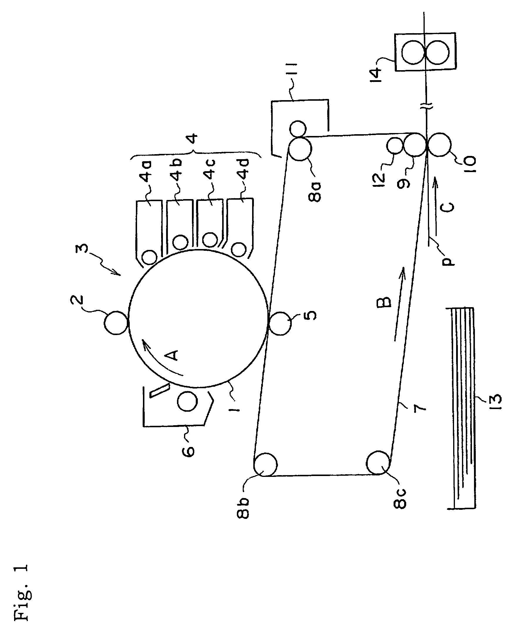
[0469]The Vivace 400 modified machine is an image forming device comprising an electrostatic latent image bearing body, charging means for charging the surface of the electrostatic latent image bearing body, electrostatic latent image-forming means of forming an electrostatic latent image on the charged surface of the electrostatic latent image bearing body, a development device, which contains the developing agent composed of the toner and carrier, for developing the electrostatic latent image with a layer of the developing agent formed on the surface of the developing agent-bearing body, to form a toner image on the surface of the electrostatic latent image bearing body, transfer means of transferring th...

example 6

[0480]A copying test was conducted in the same manner as in Example 1 except that the electrostatic latent image developing agent (6) was used in place of the electrostatic latent image developing agent (1), and the same evaluation was conducted.

[0481]The results are shown in Tables 1, 2 and 3.

example 7

[0482]A copying test was conducted in the same manner as in Example 1 except that the electrostatic latent image developing agent (7) was used in place of the electrostatic latent image developing agent (1), and the same evaluation was conducted.

[0483]The results are shown in Tables 1, 2 and 3.


PUM

PropertyMeasurementUnit
particle sizeaaaaaaaaaa
particle diameteraaaaaaaaaa

Abstract

The present invention relates to an image forming method wherein the surface of an electrophotographic photoreceptor contains a compound having an unsaturated double bond, a toner for electrostatic latent image development has a binder resin obtained by polymerizing a polymerizable monomer having a vinyl double bond, has at least one kind of metal oxide particles and/or metal nitride particles on the surface of the toner and has a shape factor SF1 of 110 to 140, and the storage of elastic modulus at 160° C. (G′(160)) of the toner for electrostatic latent image development is in a predetermined range.

Description

CROSS-REFERENCE TO RELATED APPLICATION[0001]This application claims priority under 35 USC 119 from Japanese patent Application Nos. 2003-62888 and 2003-163390, the disclosure of which is incorporated by reference herein.BACKGROUND OF THE INVENTION[0002]1. Field of the Invention[0003]The present invention relates to an image forming method wherein an electrostatic latent image formed by electrophotography, electrostatic recording etc. is visualized through the steps of development, transfer and fixation to give a suitable image.[0004]2. Description of the Related Art[0005]A method of visualizing image information via an electrostatic latent image, such as an electrophotographic method etc., is used in various fields. In the electrophotographic method, an electrostatic latent image on an electrophotographic photoreceptor (electrostatic latent image bearing body, also referred to hereinafter as “photoreceptor”) after a charging step, a light exposure step etc. is developed with a toner...

Claims


Application Information

Patent Timeline
Patent Type & Authority Patents(United States)
IPC IPC(8): G03G9/08G03G9/087G03G5/06G03G9/097G03G13/01G03G15/16G03G15/20
CPCG03G5/0607G03G13/013G03G5/0616G03G5/0627G03G5/0666G03G5/0672G03G9/08702G03G9/08713G03G9/08717G03G9/0872G03G9/08722G03G9/08724G03G9/08726G03G9/08728G03G9/08731G03G9/08733G03G9/09708G03G9/09725G03G5/0614G03G5/06147G03G5/061473G03G13/0133
Inventor SERIZAWA, MANABUYAGUCHI, HIDEKAZUKUBO, TSUTOMUYANAGIDA, KAZUHIKOSEITOKU, SHIGERUMATSUMURA, YASUOSAKAI, SUEKOTANAKA, HIROYUKI
Owner FUJIFILM BUSINESS INNOVATION CORP
Why Eureka
Try Eureka